A22-SW-11M Omron, A22-SW-11M Datasheet - Page 31
A22-SW-11M
Manufacturer Part Number
A22-SW-11M
Description
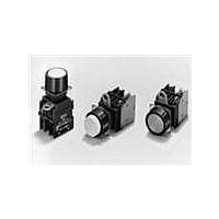
SWITCH PB MUSH MOM SPST-NO/C WHT
Manufacturer
Omron
Series
A22r
Type
Standardr
Specifications of A22-SW-11M
Circuit
DPST (1-NO, 1-NC)
Switch Function
On-Mom, Off-Mom
Contact Rating @ Voltage
10A @ 110VAC
Actuator Type
Mushroom Button
Mounting Type
Panel Mount
Termination Style
Screw Terminal
Contact Form
SPST - NC-NO
Contact Rating
10 mAmps
Actuator
Round, Mushroom
Mounting Style
Panel
Illumination
Illuminated
Illumination Color
White
Body Shape
Square
Dielectric Strength
2500 Volts
Insulation Resistance
100 MOhms
Mounting Angle
Straight
Operating Force
29.4 N
Water / Moisture Rating
IP65
Lead Free Status / RoHS Status
Lead free / RoHS Compliant
Illumination Type, Color
-
Illumination Voltage (nominal)
-
Lead Free Status / Rohs Status
Lead free / RoHS Compliant
Other names
A22SW11M


Precautions for Correct Use of Pushbutton Switches
●For the individual precautions for a Switch, refer to the precautions in the section for that Switch.
Electrical Characteristics
1. Operating Load
Inrush Current
Type of Load vs. Inrush Current
The switching load capacity of the Switch greatly varies between
AC and DC. Always be sure to apply the rated load. The control
capacity will drastically drop if it is a DC load. This is because a DC
load has no current zero-cross point, unlike an AC load. Therefore,
if an arc is generated, it may continue for a comparatively long time.
Furthermore, the current direction is always the same, which
results in a contact relocation phenomena whereby the contacts
easily stick to each other and do not separate when the surfaces of
the contacts are uneven.
Some types of load have a great difference between normal current
and inrush current. Make sure that the inrush current is within the
permissible value. The greater the inrush current in the closed circuit
is, the greater the contact abrasion or shift will be. Consequently,
contact weld, contact separation failures, or insulation failures may
result. Furthermore, the Switch may be broken or damaged.
If the load is inductive, counter-electromotive voltage will be generated.
The higher the voltage is, the higher the generated energy will be,
which will increase the abrasion of the contacts and contact relocation
phenomena. Be sure to use the Switch within the rated conditions.
Approximate control capacities are given in ratings tables, but
these alone are insufficient to guarantee correct operation. For
special types of load, with unusual switching voltage or current
waveforms, test whether correct operation is possible with the
actual load before application.
When switching for microloads (voltage or current), use a Switch
with microload specifications. The reliability of silver-plated
contacts, which are used in Switches for standard loads, will be
insufficient for microloads.
When switching microloads or very high loads that are beyond the
switching capacity of the Switch, connect a relay suitable for the load.
(A)
(A)
I
I
http://www.ia.omron.com/
Solenoid
(Approximately 10 to 20 times higher)
i (Inrush current)
Incandescent
lamp (Approximately 10 to 15 times
higher)
Motor
(Approximately
5 to 10 times
higher)
Relay
(Approxi-
mately 4 to 5
times higher)
o (Steadystate
current)
t
t
Technical Guide for Pushbutton Switches
All the performance ratings given are for operation under the following
conditions unless otherwise specified.
Inductive load: A minimum power factor of 0.4 (AC) and a maximum
Lamp load:
Motor load: An inrush current 6 times higher than the steady-state
Note: Inductive loads can cause problems especially in DC circuitry. Therefore,
2. Load Connections
Do not contact a single Switch to two power supplies that are different
in polarity or type.
Connection of Different Polarities
The power supply may short-circuit if the loads are connected in the
way shown in the "incorrect" example below.
Even in the "correct" example, note that the insulation performance of
the switch may deteriorate and the switch life may be shortened
because loads are connected to both contacts.
Connection of Different Power Supplies
The DC and AC power may be mixed for the circuit shown below.
Do not design a circuit where voltage is imposed between contacts,
otherwise contact weld may result.
Incorrect
correct
Incorrect
Incorrect
(c)Copyright OMRON Corporation 2007 All Rights Reserved.
it is essential to know the time constants (L/R) of the load.
Load
time constant of 7 ms (DC)
An inrush current 10 times higher than the steady-state
current
current
Load
AC
DC
Connect the load to the same polarity.
100 V
200 V
Load
Load
Load
Load
Load
C-2
Related parts for A22-SW-11M
Image
Part Number
Description
Manufacturer
Datasheet
Request
R

Part Number:
Description:
SWITCH PB MUSH MOM SPST-NO WHITE
Manufacturer:
Omron
Datasheet:

Part Number:
Description:
SWITCH PB MUSH MOM SPST-NC WHITE
Manufacturer:
Omron
Datasheet:
Part Number:
Description:
SWITCH PB MUSH MOM DPST-NC WHITE
Manufacturer:
Omron
Datasheet:
Part Number:
Description:
SWITCH PB MUSH MOM DPST-NO WHITE
Manufacturer:
Omron
Datasheet:
Part Number:
Description:
SWITCH PB MUSH ALT SPST-NC WHITE
Manufacturer:
Omron
Datasheet:
Part Number:
Description:
SWITCH PB MUSH ALT DPST-NC WHITE
Manufacturer:
Omron
Datasheet:
Part Number:
Description:
SWITCH PB MUSH ALT SPST-NO WHITE
Manufacturer:
Omron
Datasheet:
Part Number:
Description:
SWITCH PB MUSH ALT SPST-NO/C WHT
Manufacturer:
Omron
Datasheet:
Part Number:
Description:
SWITCH PB MUSH ALT DPST-NO WHITE
Manufacturer:
Omron
Datasheet:
Part Number:
Description:
SWITCH UNIT PB ROUND/MUSHRM WHT
Manufacturer:
Omron
Datasheet:
Part Number:
Description:
SWITCH PB RND MOM SPST-NO/NC RED
Manufacturer:
Omron
Datasheet:

Part Number:
Description:
SWITCH PB ROUND ALT SPST-NO BLUE
Manufacturer:
Omron
Datasheet:

Part Number:
Description:
SWITCH PB ROUND ALT SPST-NO BLK
Manufacturer:
Omron
Datasheet:

Part Number:
Description:
SWITCH PB ROUND ALT SPST-NO GRN
Manufacturer:
Omron
Datasheet:

Part Number:
Description:
SWITCH PB ROUND ALT SPST-NO RED
Manufacturer:
Omron
Datasheet: