A22-SW-11M Omron, A22-SW-11M Datasheet - Page 32
A22-SW-11M
Manufacturer Part Number
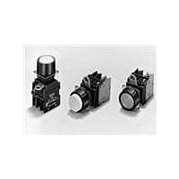
A22-SW-11M
Description
SWITCH PB MUSH MOM SPST-NO/C WHT
Manufacturer
Omron
Series
A22r
Type
Standardr
Specifications of A22-SW-11M
Circuit
DPST (1-NO, 1-NC)
Switch Function
On-Mom, Off-Mom
Contact Rating @ Voltage
10A @ 110VAC
Actuator Type
Mushroom Button
Mounting Type
Panel Mount
Termination Style
Screw Terminal
Contact Form
SPST - NC-NO
Contact Rating
10 mAmps
Actuator
Round, Mushroom
Mounting Style
Panel
Illumination
Illuminated
Illumination Color
White
Body Shape
Square
Dielectric Strength
2500 Volts
Insulation Resistance
100 MOhms
Mounting Angle
Straight
Operating Force
29.4 N
Water / Moisture Rating
IP65
Lead Free Status / RoHS Status
Lead free / RoHS Compliant
Illumination Type, Color
-
Illumination Voltage (nominal)
-
Lead Free Status / Rohs Status
Lead free / RoHS Compliant
Other names
A22SW11M


3. Contact Protective Circuit
Apply a contact protective circuit to extend the contact life, prevent
noise, and suppress the generation of carbide or nitric acid. Be sure
to apply the contact protective circuit correctly, otherwise an adverse
effect may occur. The following provides typical examples of contact
protective circuits. If the Limit Switch is used in an excessively humid
Typical Examples of Contact Protective Circuits
Do not apply contact protective circuits as shown below.
4. Switching
CR circuit
Diode method
Diode and
Zener diode
method
Varistor
method
Do not use the Switch for loads that exceed the rated switching capacity or other
contact ratings. Doing so may result in contact weld, contact separation failures,
or insulation failures. Furthermore, the Switch may be broken or damaged.
Do not touch the charged switch terminals while power is supplied,
otherwise an electric shock may be received.
The life of the Switch varies greatly with switching conditions.
Before using the Switch, be sure to test the Switch under actual
conditions. Make sure that the number of switching operations is
within the permissible range. If a deteriorated Switch is used
continuously, insulation failures, contact weld, contact failures,
switch damage, or switch burnout may result.
Power
supply
C
Circuit example
Load
Power
supply
Power
supply
Power
supply
Power
supply
http://www.ia.omron.com/
This circuit effectively
suppresses arcs when the
contacts are OFF. The
capacitor will be charged,
however, when the contacts
are OFF. Consequently,
when the contacts are ON
again, short-circuited current
from the capacitance may
cause contact weld.
Power
supply
C
C
R
R
Inductive
load
Inductive
load
Inductive
load
Inductive
load
Inductive
load
Yes Yes
Yes Yes
Applicable
AC
No
No
*
current
Yes
Yes
Yes
DC
*When AC is switched, the load impedance
must be lower than the CR impedance.
The operating time will be greater if the load
is a relay or solenoid. Connecting the CR
circuit in parallel to the load is effective when
the power supply voltage is 24 or 48 V and in
parallel to the contacts when the power
supply voltage is 100 to 200 V.
Energy stored in the coil is changed into
current by the diode connected in parallel to
the load. Then the current flowing to the coil
is consumed and Joule heat is generated by
the resistance of the inductive load. The
reset time delay with this method is longer
than that in the CR method.
This method will be effective if the reset time
delay caused by the diode method is too
long.
This method makes use of constant-voltage
characteristic of the varistor so that no
high-voltage is imposed on the contacts.
This method causes a reset time delay.
Connecting a varistor in parallel to the load is
effective when the supply voltage is 24 to 48
V and in parallel to the contacts when the
supply voltage is 100 to 200 V.
Technical Guide for Pushbutton Switches
Power
supply
C
Feature and details
Load
This circuit effectively sup-
presses arcs when the
contacts are OFF. When the
contacts are ON again,
however, charge current will
flow to the capacitor, which
may result in contact weld.
location for switching a load that easily generates arcs, such as an
inductive load, the arcs may generate NOx, which will change into
HNO
may corrode and the Limit Switch may fail. Be sure to select the ideal
contact preventive circuit from the following.
Do not apply excessive or incorrect voltages to the Switch or
incorrectly wire the terminals. Otherwise, the Switch may not
function properly and have an adverse effect on external circuitry.
Furthermore, the Switch itself may become damaged or burnt.
Do not use the Switch in locations where flammable or explosive
gases are present. Otherwise switching arcs or heat radiation may
cause a fire or explosion.
Do not drop or disassemble the Switch, otherwise it may not be
capable of full performance. Furthermore, it may be broken or
burnt.
3
if it reacts with moisture. Consequently, the internal metal parts
(c)Copyright OMRON Corporation 2007 All Rights Reserved.
C: 1 to 0.5 F
R: 0.5 to 1
The values may change according to the
characteristics of the load. The capacitor
suppresses the spark discharge of current
when the contacts are open. The resistor
limits the inrush current when the contacts
are closed again. Consider the roles of the
capacitor and resistor and determine ideal
capacitance and resistance values through
testing. Basically, use a capacitor with a
dielectric strength between 200 and 300 V.
When AC is switched, make sure that the
capacitor has no polarity.
The diode must withstand a peak inverse
voltage 10 times higher than the circuit
voltage and a forward current as high or
higher than the load current.
Use a Zener diode with a Zener voltage that
is approximately 1.2
as, depending on the environment, the load
may not operate.
Switching a DC inductive load is usually
more difficult than switching a resistive
load. By using an appropriate contact
protective circuit, however, switching a DC
inductive load will be as easy as switching a
resistive load.
Element selection
switching voltage (V)
switching current (A)
---
power supply voltage
C-3
Related parts for A22-SW-11M
Image
Part Number
Description
Manufacturer
Datasheet
Request
R

Part Number:
Description:
SWITCH PB MUSH MOM SPST-NO WHITE
Manufacturer:
Omron
Datasheet:

Part Number:
Description:
SWITCH PB MUSH MOM SPST-NC WHITE
Manufacturer:
Omron
Datasheet:
Part Number:
Description:
SWITCH PB MUSH MOM DPST-NC WHITE
Manufacturer:
Omron
Datasheet:
Part Number:
Description:
SWITCH PB MUSH MOM DPST-NO WHITE
Manufacturer:
Omron
Datasheet:
Part Number:
Description:
SWITCH PB MUSH ALT SPST-NC WHITE
Manufacturer:
Omron
Datasheet:
Part Number:
Description:
SWITCH PB MUSH ALT DPST-NC WHITE
Manufacturer:
Omron
Datasheet:
Part Number:
Description:
SWITCH PB MUSH ALT SPST-NO WHITE
Manufacturer:
Omron
Datasheet:
Part Number:
Description:
SWITCH PB MUSH ALT SPST-NO/C WHT
Manufacturer:
Omron
Datasheet:
Part Number:
Description:
SWITCH PB MUSH ALT DPST-NO WHITE
Manufacturer:
Omron
Datasheet:
Part Number:
Description:
SWITCH UNIT PB ROUND/MUSHRM WHT
Manufacturer:
Omron
Datasheet:
Part Number:
Description:
SWITCH PB RND MOM SPST-NO/NC RED
Manufacturer:
Omron
Datasheet:

Part Number:
Description:
SWITCH PB ROUND ALT SPST-NO BLUE
Manufacturer:
Omron
Datasheet:

Part Number:
Description:
SWITCH PB ROUND ALT SPST-NO BLK
Manufacturer:
Omron
Datasheet:

Part Number:
Description:
SWITCH PB ROUND ALT SPST-NO GRN
Manufacturer:
Omron
Datasheet:

Part Number:
Description:
SWITCH PB ROUND ALT SPST-NO RED
Manufacturer:
Omron
Datasheet: