PIC18LF24K22-I/SS Microchip Technology, PIC18LF24K22-I/SS Datasheet - Page 166
PIC18LF24K22-I/SS
Manufacturer Part Number
PIC18LF24K22-I/SS
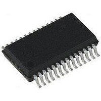
Description
IC PIC MCU 16KB FLASH 28SSOP
Manufacturer
Microchip Technology
Series
PIC® XLP™ 18Fr
Specifications of PIC18LF24K22-I/SS
Core Size
8-Bit
Program Memory Size
16KB (8K x 16)
Core Processor
PIC
Speed
64MHz
Connectivity
I²C, SPI, UART/USART
Peripherals
Brown-out Detect/Reset, HLVD, POR, PWM, WDT
Number Of I /o
24
Program Memory Type
FLASH
Eeprom Size
256 x 8
Ram Size
768 x 8
Voltage - Supply (vcc/vdd)
1.8 V ~ 3.6 V
Data Converters
A/D 19x10b
Oscillator Type
Internal
Operating Temperature
-40°C ~ 85°C
Package / Case
28-SSOP (0.200", 5.30mm Width)
Controller Family/series
PIC18
No. Of I/o's
25
Eeprom Memory Size
256Byte
Ram Memory Size
768Byte
Cpu Speed
64MHz
No. Of Timers
7
Lead Free Status / RoHS Status
Lead free / RoHS Compliant


PIC18(L)F2X/4XK22
12.8
The
increments to FFFFh and rolls over to 0000h. When
Timer1/3/5 rolls over, the Timer1/3/5 interrupt flag bit of
the PIR1/2/5 register is set. To enable the interrupt on
rollover, you must set these bits:
• TMRxON bit of the TxCON register
• TMRxIE bits of the PIE1, PIE2 or PIE5 registers
• PEIE/GIEL bit of the INTCON register
• GIE/GIEH bit of the INTCON register
The interrupt is cleared by clearing the TMRxIF bit in
the Interrupt Service Routine.
For more information on selecting high or low priority
status for the Timer1/3/5 Overflow Interrupt, see
Section 9.0
12.9
Timer1/3/5 can only operate during Sleep when set up
in Asynchronous Counter mode. In this mode, an
external crystal or clock source can be used to
increment the counter. To set up the timer to wake the
device:
• TMRxON bit of the TxCON register must be set
• TMRxIE bit of the PIE1/2/5 register must be set
• PEIE/GIEL bit of the INTCON register must be set
• TxSYNC bit of the TxCON register must be set
• TMRxCS bits of the TxCON register must be
• TxSOSCEN bit of the TxCON register must be
The device will wake-up on an overflow and execute
the next instruction. If the GIE/GIEH bit of the INTCON
register is set, the device will call the Interrupt Service
Routine.
The secondary oscillator will continue to operate in
Sleep regardless of the TxSYNC bit setting.
DS41412D-page 166
Note:
configured
configured
Timer1/3/5
Timer1/3/5 Interrupt
Timer1/3/5 Operation During Sleep
The TMRxH:TMRxL register pair and the
TMRxIF bit should be cleared before
enabling interrupts.
“Interrupts”.
register
pair
(TMRxH:TMRxL)
Preliminary
12.10 ECCP/CCP Capture/Compare Time
The CCP modules use the TMRxH:TMRxL register pair
as the time base when operating in Capture or
Compare mode.
In Capture mode, the value in the TMRxH:TMRxL
register pair is copied into the CCPRxH:CCPRxL
register pair on a configured event.
In Compare mode, an event is triggered when the value
CCPRxH:CCPRxL register pair matches the value in
the TMRxH:TMRxL register pair. This event can be a
Special Event Trigger.
For
“Capture/Compare/PWM Modules”.
12.11 ECCP/CCP Special Event Trigger
When any of the CCP’s are configured to trigger a
special event, the trigger will clear the TMRxH:TMRxL
register pair. This special event does not cause a
Timer1/3/5 interrupt. The CCP module may still be
configured to generate a CCP interrupt.
In this mode of operation, the CCPRxH:CCPRxL
register pair
Timer1/3/5.
Timer1/3/5 should be synchronized and F
be selected as the clock source in order to utilize the
Special Event Trigger. Asynchronous operation of
Timer1/3/5 can cause a Special Event Trigger to be
missed.
In the event that a write to TMRxH or TMRxL coincides
with a Special Event Trigger from the CCP, the write will
take precedence.
For more information, see Section 17.2.8 “Special
Event Trigger”.
more
Base
becomes the
information,
2010 Microchip Technology Inc.
period
see
Section 14.0
OSC
register
/4 should
for
Related parts for PIC18LF24K22-I/SS
Image
Part Number
Description
Manufacturer
Datasheet
Request
R

Part Number:
Description:
Manufacturer:
Microchip Technology Inc.
Datasheet:
Part Number:
Description:
Manufacturer:
Microchip Technology Inc.
Datasheet:
Part Number:
Description:
Manufacturer:
Microchip Technology Inc.
Datasheet:
Part Number:
Description:
Manufacturer:
Microchip Technology Inc.
Datasheet:
Part Number:
Description:
Manufacturer:
Microchip Technology Inc.
Datasheet:
Part Number:
Description:
Manufacturer:
Microchip Technology Inc.
Datasheet:
Part Number:
Description:
Manufacturer:
Microchip Technology Inc.
Datasheet:
Part Number:
Description:
Manufacturer:
Microchip Technology Inc.
Datasheet: