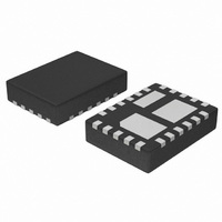
NUS6160MNTWG ON Semiconductor, NUS6160MNTWG Datasheet - Page 4

NUS6160MNTWG
Manufacturer Part Number
NUS6160MNTWG
Description
IC OVP LOW PRO W/MOSFET 22-QFN
Manufacturer
ON Semiconductor
Datasheet
1.NUS6160MNTWG.pdf
(13 pages)
Specifications of NUS6160MNTWG
Voltage - Working
1.2 ~ 20V
Technology
Mixed Technology
Number Of Circuits
1
Applications
General Purpose
Package / Case
22-TQFN Exposed Pad
Lead Free Status / RoHS Status
Lead free / RoHS Compliant
Power (watts)
-
Voltage - Clamping
-
PIN DESCRIPTION
2, 16, 17,
4, 5, 6, 7
9, 11, 13
21, 22
Pin
10
12
14
15
18
19
20
1
3
8
Source FET
Source FET
Drain FET
Gate FET
Drain FET
Gate FET
Name
FLAG
Gnd
N/C
N/C
Out
EN
In
REG
REG
SW
SW
REG
SW
This pin is the output of the internal OVP chip. It must be connected to the source of the upper
FET (Pin 8).
This pin is the gate of the upper FET which is normally used for a switch in series with the battery.
It is controlled by the PMU.
These pins are the drain of the upper FET. For the lowest on resistance connect all pins together.
This set of pins must be connected to the source of the lower (regulator) FET, Pin 10.
This pin is the source of the upper FET and must be connected to the output pin of the internal
OVP chip (Pin 1).
These pins are the drain of the lower FET which is normally used for the regulation function. It
connects to the positive terminal of the battery.
This pin is the source of the lower FET and must be connected to the drain pins of the upper FET.
This pin has no internal connections and is isolated from all internal circuitry within the chip.
This pin is the gate of the lower FET which is normally used for the regulation function in series
with the battery. It is controlled by the PMU.
The fault flag is an open drain output and therefore requires a pullup resistor. The FLAG pin will be
driven low when the input voltage exceeds the OVLO trip level.
These pins are connected to the ground of the analog chip. This is a medium impedance
connection and should not be used for the ground signal. These pins should either be left floating
or connected to ground, but not any other potential. If these pins are connected to ground, the
ground pin (19) must still be used.
The ENABLE pin must be held low for normal operation. When this pin is tied high the unit will be
shut down. The state of the enable pin has no impact on the FAULT pin.
This is the ground reference pin for the internal OVP chip.
This pin is the input to the internal OVP chip and connects to the wall, or car adaptor.
http://onsemi.com
4
Description


