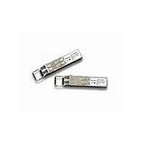
AFBR-5715PZ Avago Technologies US Inc., AFBR-5715PZ Datasheet - Page 3

AFBR-5715PZ
Manufacturer Part Number
AFBR-5715PZ
Description
Fiber Optic Transmitters, Receivers, Transceivers Transceiver
Manufacturer
Avago Technologies US Inc.
Type
TX/RXr
Series
-r
Specifications of AFBR-5715PZ
Function
Designed for those applications requiring DMI features.
Product
Transceiver
Data Rate
1.25 GBd
Wavelength
850 nm
Maximum Rise Time
0.26 ns/0.22 ns (Typ)
Maximum Fall Time
0.26 ns/0.22 ns (Typ)
Pulse Width Distortion
0.227 ns (Max)/0.266 ns (Max)
Operating Supply Voltage
3.135 V to 3.465 V
Maximum Operating Temperature
+ 85 C
Minimum Operating Temperature
- 10 C
Package / Case
SFP
Mounting Type
SFP
Voltage - Supply
3.135 V ~ 3.465 V
Connector Type
LC Duplex
Applications
Ethernet
Optical Fiber Type
TX/RX
Data Transfer Rate
1250MBd
Optical Rise Time
0.26/0.22ns
Optical Fall Time
0.26/0.22ns
Jitter
0.227/0.266ns
Operating Temperature Classification
Commercial
Peak Wavelength
850nm
Package Type
SFP
Operating Supply Voltage (min)
3.135V
Operating Supply Voltage (typ)
3.3V
Operating Supply Voltage (max)
3.465V
Operating Temp Range
-10C to 85C
Mounting
Snap Fit To Panel
Pin Count
20
Package
20SFP
Rise Time
0.26/0.22(Typ) ns
Lead Free Status / RoHS Status
Lead free / RoHS Compliant
For Use With
Multimode Glass
Lead Free Status / RoHS Status
Lead free / RoHS Compliant, Lead free / RoHS Compliant
Available stocks
Company
Part Number
Manufacturer
Quantity
Price
Company:
Part Number:
AFBR-5715PZ
Manufacturer:
Avago Technologies
Quantity:
135
Installation
The AFBR-571xZ can be installed in or removed from any
MSA-compliant Pluggable Small Form Factor port regard-
less of whether the host equipment is operating or not.
The module is simply inserted, electrical-interface fi rst,
under fi nger-pressure. Controlled hot-plugging is ensured
by 3-stage pin sequencing at the electrical interface. This
printed circuit board card-edge connector is depicted in
Figure 2.
As the module is inserted, fi rst contact is made by the
housing ground shield, discharging any potentially com-
ponent-damaging static electricity. Ground pins engage
next and are followed by Tx and Rx power supplies. Finally,
signal lines are connected. Pin functions and sequencing
are listed in Table 2.
Transmitter Section
The transmitter section includes the Transmitter Optical
Sub assembly (TOSA) and laser driver circuitry. The TOSA,
containing an 850 nm VCSEL (Vertical Cavity Surface Emit-
ting Laser) light source, is located at the optical interface and
mates with the LC optical connector. The TOSA is driven by
a custom IC, which converts diff erential logic signals into an
analog laser diode drive current. This Tx driver circuit regu-
lates the optical power at a constant level provided the data
pattern is DC balanced (8B10B code for example).
Transmit Disable (Tx_Disable)
The AFBR-571xZ accepts a TTL and CMOS compatible
transmit disable control signal input (pin 3) which shuts
down the transmitter optical output. A high signal imple-
ments this function while a low signal allows normal
transceiver operation. In the event of a fault (e.g. eye
safety circuit activated), cycling this control signal resets
the module as depicted in Figure 6. An internal pull-up
resistor disables the transceiver transmitter until the host
pulls the input low. Host systems should allow a 10ms
interval between successive assertions of this control
signal. Tx_Disable can also be asserted via the 2-wire serial
interface (address A2h, byte 110, bit 6) and monitored
(address A2h, byte 110, bit 7).
The contents of A2h, byte 110, bit 6 are logic OR’d with
hardware Tx_Disable (pin 3) to control transmitter opera-
tion.
3
Transmit Fault (Tx_Fault)
A catastrophic laser fault will activate the transmitter signal,
TX_FAULT, and disable the laser. This signal is an open collec-
tor output (pull-up required on the host board). A low signal
indicates normal laser operation and a high signal indicates
a fault. The TX_FAULT will be latched high when a laser fault
occurs and is cleared by toggling the TX_DISABLE input or
power cycling the transceiver. The transmitter fault condition
can also be monitored via the 2-wire serial interface (address
A2, byte 110, bit 2).
Eye Safety Circuit
The AFBR-571xZ provides Class 1 eye safety by design and
has been tested for compliance with the requirements
listed in Table 1. The eye safety circuit continu ously moni-
tors optical output power levels and will disable the trans-
mitter and assert a TX_FAULT signal upon detecting an
unsafe condition. Such unsafe conditions can be created
by inputs from the host board (Vcc fl uxuation, unbalanced
code) or faults within the module.
Receiver Section
The receiver section includes the Receiver Optical Subas-
sembly (ROSA) and amplifi cation/quantization circuitry. The
ROSA, containing a PIN photodiode and custom trans-im-
pedance preamplifi er, is located at the optical interface and
mates with the LC optical connector. The ROSA is mated to
a custom IC that provides post-amplifi cation and quantiza-
tion. Also included is a Loss Of Signal (LOS) detection circuit.
Receiver Loss of Signal (Rx_LOS)
The Loss Of Signal (LOS) output indicates an unusable
optical input power level. The Loss Of Signal thresholds
are set to indicate a defi nite optical fault has occurred
(e.g., disconnected or broken fi ber connection to receiver,
failed transmitter, etc.).
The post-amplifi cation IC includes transition detection
circuitry which monitors the ac level of incoming optical
signals and provides a TTL/CMOS compatible status signal
to the host (pin 8). An adequate optical input results in a
low Rx_LOS output while a high Rx_LOS output indicates
an unusable optical input. The Rx_LOS thresholds are fac-
tory-set so that a high output indicates a defi nite optical
fault has occurred. For the AFBR-5715Z family, Rx_LOS can
also be monitored via the 2-wire serial interface (address
A2h, byte 110, bit 1).


