LFXP2-5E-B-EVN Lattice, LFXP2-5E-B-EVN Datasheet - Page 4
LFXP2-5E-B-EVN
Manufacturer Part Number
LFXP2-5E-B-EVN
Description
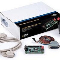
MCU, MPU & DSP Development Tools LatticeXP2 Brevia Dev kit
Manufacturer
Lattice
Series
-r
Type
FPGAr
Datasheets
1.LFXP2-5E-B-EVN.pdf
(25 pages)
2.LFXP2-5E-B-EVN.pdf
(4 pages)
3.LFXP2-5E-B-EVN.pdf
(4 pages)
Specifications of LFXP2-5E-B-EVN
Processor To Be Evaluated
LFXP2-5E-6TN144C
Data Bus Width
8 bit
Interface Type
RS-232, JTAG, SPI
Operating Supply Voltage
3.3 V
Silicon Manufacturer
Lattice Semiconductor
Silicon Family Name
LatticeXP2
Kit Contents
Evaluation Board, USB Cables, AC Adapter, Quick Start Guide
Features
Serial RS232 Interface, JTAG Interface
Svhc
No
Rohs Compliant
Yes
Contents
Board, Cables, Documentation, Power Supply
Lead Free Status / RoHS Status
Lead free / RoHS Compliant
For Use With/related Products
LFXP2-5E-6TN144C
Available stocks
Company
Part Number
Manufacturer
Quantity
Price
Company:

Part Number:
LFXP2-5E-B-EVN
Manufacturer:
Lattice
Quantity:
8


Lattice Semiconductor
The demo design integrates the following
• LatticeMico8 Microcontroller (RD1026)
• WISHBONE UART (RD1042)
• SPI WISHBONE Controller (RD1044)
• LatticeMico8 to WISHBONE Interface Adapter (RD1043)
Firmware running on the LatticeMico8 demonstrates control logic for the peripherals connected to a shared on-chip
WISHBONE bus and communication between the LatticeXP2 Brevia Evaluation Board and a host PC connected to
the RS232 cable.
Figure 2. Demo_LatticeXP2_Brevia_SoC Block Diagram
Set Up a VT100/ANSI Terminal Emulator
The Demo_LatticeXP2_Brevia_SoC preloaded in the LatticeXP2 Brevia Evaluation Board is operated by interact-
ing with a monitor program. The monitor program sends and receives data across the RS232 communications port
on the LatticeXP2 Brevia Evaluation Board. It is necessary to start and configure a VT100 or ANSI style terminal
emulator program like HyperTerminal (Windows) or Minicom (Linux).
The RS232 port on the LatticeXP2 Brevia Evaluation Board is configured to operate at 115.2Kbps, 8 data bits, 1
stop bit, and no parity, and no flow control. Once the terminal emulator is running on the host computer, and the
RS232 cable is attached between the host computer and the LatticeXP2 Brevia Evaluation Board you will see the
following banner displayed when the board is powered, or following a RESET button assertion.
PC Host
RS-232
Lattice reference
LatticeXP2 Brevia Evaluation Board
LatticeXP2 FPGA
UART
Flash Memory
SPI Memory
4
SPI 2-Mbit
Controller
SPI
designs:
WISHBONE Bus
LatticeMico8
LatticeXP2 Brevia Development Kit
LED Bank
SRAM Memory
SRAM
SRAM 1-Mbit
Controller
Memory
Switch Bank
User’s Guide
Related parts for LFXP2-5E-B-EVN
Image
Part Number
Description
Manufacturer
Datasheet
Request
R

Part Number:
Description:
FPGA - Field Programmable Gate Array 5K LUTs 146I/O Inst- on DSP 1.2V -5 Spd
Manufacturer:
Lattice
Datasheet:

Part Number:
Description:
Programmable Logic IC Development Tools Lattice XP2 Brevia Dev Kit
Manufacturer:
Lattice
Datasheet:

Part Number:
Description:
FPGA - Field Programmable Gate Array 5K LUTs 172 I/O Inst on DSP 1.2V -5 Spd
Manufacturer:
Lattice
Datasheet:
Part Number:
Description:
FPGA - Field Programmable Gate Array 5K LUTs 100 I/O Inst on DSP 1.2V -5 Spd
Manufacturer:
Lattice
Datasheet:

Part Number:
Description:
FPGA - Field Programmable Gate Array 5K LUTs 172I/O Inst- on DSP 1.2V -5 Spd
Manufacturer:
Lattice
Datasheet:

Part Number:
Description:
FPGA - Field Programmable Gate Array 5K LUTs 100I/O Inst- on DSP 1.2V -5 Spd
Manufacturer:
Lattice
Datasheet:

Part Number:
Description:
FPGA LatticeXP2 Family 5000 Cells Flash Technology 1.2V 256-Pin FTBGA
Manufacturer:
LATTICE SEMICONDUCTOR
Datasheet:
Part Number:
Description:
FPGA LatticeXP2 Family 5000 Cells Flash Technology 1.2V 256-Pin FTBGA
Manufacturer:
LATTICE SEMICONDUCTOR
Datasheet:
Part Number:
Description:
IC DSP 5KLUTS 100I/O 144TQFP
Manufacturer:
Lattice
Datasheet:
Part Number:
Description:
IC DSP 5KLUTS 86I/O 132CSBGA
Manufacturer:
Lattice
Datasheet:
Part Number:
Description:
IC DSP 5KLUTS 86I/O 132CSBGA
Manufacturer:
Lattice
Datasheet:
Part Number:
Description:
IC DSP 5KLUTS 146I/O 208PQFP
Manufacturer:
Lattice
Datasheet:
Part Number:
Description:
IC DSP 5KLUTS 146I/O 208PQFP
Manufacturer:
Lattice
Datasheet:
Part Number:
Description:
IC DSP 5KLUTS 172I/O 256FTBGA
Manufacturer:
Lattice
Datasheet:
Part Number:
Description:
IC FPGA 5KLUTS 86I/O 132-BGA
Manufacturer:
Lattice
Datasheet: