MPC8536EAVTAVL Freescale Semiconductor, MPC8536EAVTAVL Datasheet - Page 100
MPC8536EAVTAVL
Manufacturer Part Number
MPC8536EAVTAVL
Description
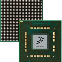
Microprocessors (MPU) PQ38S 8536 SQUID
Manufacturer
Freescale Semiconductor
Datasheet
1.MPC8536EBVTAQG.pdf
(126 pages)
Specifications of MPC8536EAVTAVL
Processor Series
MPC85xx
Core
e500
Data Bus Width
32 bit
Maximum Clock Frequency
1500 MHz
Operating Supply Voltage
3.3 V
Maximum Operating Temperature
+ 90 C
Mounting Style
SMD/SMT
Interface Type
I2C, SPI, UART
Minimum Operating Temperature
0 C
Package / Case
FCPBGA-783
Lead Free Status / RoHS Status
Lead free / RoHS Compliant
Available stocks
Company
Part Number
Manufacturer
Quantity
Price
Company:

Part Number:
MPC8536EAVTAVLA
Manufacturer:
Freescale Semiconductor
Quantity:
10 000


V
T
T
MAX-JITTER
T
V
V
IDLE-DELTA
V
V
V
V
I
T
PCI Express
100
TX-SHORT
TX-EYE
TX-EYE-MEDIAN-to-
TX-RISE
TX-IDLE-MIN
TX-DE-RATIO
TX-CM-ACp
TX-CM-DC-ACTIVE-
TX-CM-DC-LINE-DELTA
TX-IDLE-DIFFp
TX-RCV-DETECT
TX-DC-CM
Symbol
, T
TX-FALL
MPC8535E PowerQUICC III Integrated Processor Hardware Specifications, Rev. 3
Table 71. Differential Transmitter (TX) Output Specifications (continued)
De- Emphasized
Differential Output
Voltage (Ratio)
Minimum TX Eye
Width
Maximum time
between the jitter
median and
maximum
deviation from the
median.
D+/D- TX Output
Rise/Fall Time
RMS AC Peak
Common Mode
Output Voltage
Absolute Delta of
DC Common
Mode Voltage
During L0 and
Electrical Idle
Absolute Delta of
DC Common
Mode between D+
and D–
Electrical Idle
differential Peak
Output Voltage
The amount of
voltage change
allowed during
Receiver Detection
The TX DC
Common Mode
Voltage
TX Short Circuit
Current Limit
Minimum time
spent in Electrical
Idle
Parameter
0.125
–3.0
0.70
Min
50
—
—
—
—
0
0
0
0
Nom
–3.5
—
—
—
—
—
—
—
—
—
—
—
Max
–4.0
0.15
100
600
3.6
20
25
20
90
—
—
—
Units
mV
mV
mV
mV
mV
mA
dB
UI
UI
UI
UI
V
Ratio of the V
bits after a transition divided by the V
first bit after a transition. See Note 2.
The maximum Transmitter jitter can be derived as
T
See Notes 2 and 3.
Jitter is defined as the measurement variation of the
crossing points (V
recovered TX UI. A recovered TX UI is calculated over
3500 consecutive unit intervals of sample data. Jitter
is measured using all edges of the 250 consecutive UI
in the center of the 3500 UI used for calculating the TX
UI. See Notes 2 and 3.
See Notes 2 and 5
V
V
See Note 2
|V
Idle)
V
V
[Electrical Idle]
See Note 2.
|V
V
V
See Note 2.
V
See Note 2.
The total amount of voltage change that a transmitter
can apply to sense whether a low impedance
Receiver is present. See Note 6.
The allowed DC Common Mode voltage under any
conditions. See Note 6.
The total current the Transmitter can provide when
shorted to its ground
Minimum time a Transmitter must be in Electrical Idle
Utilized by the Receiver to start looking for an
Electrical Idle Exit after successfully receiving an
Electrical Idle ordered set
TX-MAX-JITTER
TX-CM-ACp
TX-CM-DC
TX-CM-DC
TX-CM-Idle-DC
TX-CM-DC-D+
TX-CM-DC-D-
TX-IDLE-DIFFp
TX-CM-DC (during L0)
TX-CM-DC-D+
|<=100 mV
= DC
= DC
= RMS(|V
= DC
TX-DIFFp-p
= DC
= DC
– V
= |V
= 1 – T
(avg)
(avg)
TX-CM-DC-D-
TX-DIFFp-p
(avg)
TX-IDLE-D+
(avg)
(avg)
Comments
– V
of |V
of |V
TXD+
TX-EYE
of |V
of the second and following
of |V
TX-CM-Idle-DC (During Electrical
of |V
TX-D+
TX-D+
+V
Freescale Semiconductor
TX-D-
= 0 V) in relation to a
TX-D+
TX-D+
= 0.3 UI.
-V
| <= 25 mV
TXD-
+V
+V
TX-IDLE-D-
|
|
|/2 – V
TX-D-
TX-D-
+ V
TX-DIFFp-p
TX-D-
|/2
|/2 [L0]
TX-CM-DC
| <= 20 mV
|/2
of the
)
Related parts for MPC8536EAVTAVL
Image
Part Number
Description
Manufacturer
Datasheet
Request
R

Part Number:
Description:
Mpc8536e Powerquicctm Iii Integrated Processor Hardware Specifications
Manufacturer:
Freescale Semiconductor, Inc
Datasheet:

Part Number:
Description:
HARDWARE/SOFTWARE ANDROID OS
Manufacturer:
Freescale Semiconductor
Datasheet:

Part Number:
Description:
MCU, MPU & DSP Development Tools COMEXPRESS BASED MPC8536
Manufacturer:
Freescale Semiconductor
Datasheet:
Part Number:
Description:
Manufacturer:
Freescale Semiconductor, Inc
Datasheet:
Part Number:
Description:
Manufacturer:
Freescale Semiconductor, Inc
Datasheet:
Part Number:
Description:
Manufacturer:
Freescale Semiconductor, Inc
Datasheet:
Part Number:
Description:
Manufacturer:
Freescale Semiconductor, Inc
Datasheet:
Part Number:
Description:
Manufacturer:
Freescale Semiconductor, Inc
Datasheet:
Part Number:
Description:
Manufacturer:
Freescale Semiconductor, Inc
Datasheet:
Part Number:
Description:
Manufacturer:
Freescale Semiconductor, Inc
Datasheet:
Part Number:
Description:
Manufacturer:
Freescale Semiconductor, Inc
Datasheet:
Part Number:
Description:
Manufacturer:
Freescale Semiconductor, Inc
Datasheet:
Part Number:
Description:
Manufacturer:
Freescale Semiconductor, Inc
Datasheet:
Part Number:
Description:
Manufacturer:
Freescale Semiconductor, Inc
Datasheet:
Part Number:
Description:
Manufacturer:
Freescale Semiconductor, Inc
Datasheet: