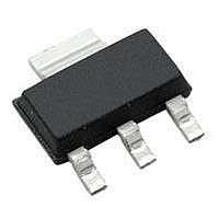
HV100K5-G Supertex, HV100K5-G Datasheet - Page 6

HV100K5-G
Manufacturer Part Number
HV100K5-G
Description
Hot Swap & Power Distribution Negative
Manufacturer
Supertex
Datasheet
1.HV100K5-G.pdf
(8 pages)
Specifications of HV100K5-G
Mounting Style
SMD/SMT
Package / Case
SOT-223
Product
Power Distribution
Supply Voltage (min)
- 72 V
Operating Temperature Range
- 40 C to + 85 C
Supply Current
1 mA
Lead Free Status / RoHS Status
Lead free / RoHS Compliant
For most applications and pass elements, the HV100 provides
adequate limiting of the maximum current to prevent damage
without the need for any external components. The 2.5s delay
of the auto-retry circuit provides time for the pass element to
cool between attempts.
Auto-Retry
Not only does the HV100 provide short circuit protection in a
3-pin package, they also includes a 2.5s built in auto-restart
timer. The HV100 will continuously try to turn on the system
every 2.5s, providing sufficient time for the pass element to
cool down after each attempt.
Calculating Inrush Current
As can be seen in the diagram below, for a standard pass
element, the HV100 will normalize the hotswap time period
against load capacitance. For this reason the current limit will
increase with increasing value of the load capacitance.
Inrush can be calculated from the following formula:
I
INRUSH(PEAK)
= (C
ISS
/ C
RSS
) * 2.5e3 * C
●
1235 Bordeaux Drive, Sunnyvale, CA 94089
LOAD
6
This is a surprisingly consistent result because for most
MOSFETs of a particular type the ratio of C
tively constant (though notice from the plot that there is some
variation) even while the absolute value of these and other
quantities vary. Based on this, the inrush current will vary
primarily with C
particularly easy because once the pass element is chosen,
the period is fixed and the inrush varies with C
Programming the HV100
The HV100 requires no external components other than a
pass element to provide the functionality described thus far.
In some applications it may be useful to use external compo-
nents to adjust the maximum allowable inrush current, adjust
UVLO, or to provide additional GATE clamping if the supply
rails have rise times below 1.0ms.
All of the above are possible with a minimum number of ex-
ternal components.
i)
ii) To increase undervoltage lockout simply connect a Zener
iii) If the V
iv) To limit the peak current during a short circuit, a resistor
To adjust inrush current with an external component
simply connect a capacitor (C
the MOSFET. The inrush calculation then becomes:
I
Note that a resistor (approximately 10KΩ) needs to be
added in series with C
loop and limit the spurious turn on which is now enhanced
by the larger divider element.
diode in series with the VPP pin.
desirable to connect a capacitor from GATE to source
of the MOSFET to provide a path for the power applica-
tion transient spike, which is now too fast for the internal
clamping mechanism.
in series with the source of the MOSFET may help.
INRUSH(PEAK)
●
PP
Tel: 408-222-8888
rises particularly fast (>48e6V/s) then it may be
= (C
LOAD
FB
. This makes designing with the HV100
+ C
ISS
FB
)/(C
to create a zero in the feedback
●
www.supertex.com
RSS
FB
+ C
) from drain to GATE of
FB
) * 2.5e3 * C
ISS
LOAD
/ C
HV100
RSS
only.
LOAD
is rela-


