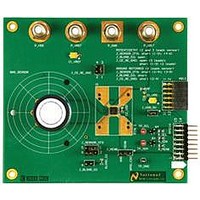
SPIO-4/NOPB National Semiconductor, SPIO-4/NOPB Datasheet - Page 10

SPIO-4/NOPB
Manufacturer Part Number
SPIO-4/NOPB
Description
BOARD INTERFACE FOR AFE
Manufacturer
National Semiconductor
Datasheet
1.SPIO-4NOPB.pdf
(26 pages)
Specifications of SPIO-4/NOPB
Main Purpose
Interface, Analog Front End (AFE)
Embedded
Yes, MCU, 32-Bit
Utilized Ic / Part
SAM3U, XC6SLX16
Primary Attributes
USB Powered or External Supply
Secondary Attributes
GUI, I2C, SPI, USB Interfaces
Accessory Type
Digital Interface Board
Msl
MSL 1 - Unlimited
Lead Free Status / RoHS Status
Lead free / RoHS Compliant
Other names
SPI0-4/NOPB
SPI0-4/NOPB
SPI0-4/NOPB
Available stocks
Company
Part Number
Manufacturer
Quantity
Price
Company:
Part Number:
SPIO-4/NOPB
Manufacturer:
National Semiconductor
Quantity:
135
National Semiconductor
Pins 1-16 form the GPSI-16 subset:
Pin
10
11
12
13
14
#
1
2
3
4
5
6
7
8
9
SCS0_A~
SerialBus A – Chip Select for device 0.
GND
SCK_A
Serial Bus A – Serial Clock from the master to the device.
DUT_Present~
The DUT board shall ground this pin. The SPIO-4 senses this pin to
determine the DUT board’s presence.
SMISO_A
Serial Bus A – Data from the slave (device) to the master. The device
may implement this as a tri-state signal that can be driven by multiple
devices on Serial Bus A in a bussed fashion. The pull-up resistor, if
required, is on the DUT board.
Dev_INT~/SDRDY_A~
In certain applications, if required, this pin serves as the DRDY~
signal from the DUT to the SPIO-4. In other cases, this pin may be a
general interrupt pin from the device to the SPIO-4.
On the SPIO-4 board this signal connects to an interrupt pin on the
microcontroller.
SMOSI_A
Serial Bus A – Data from the master to the slave (device).
SCS1_A~
SerialBus A – Chip Select for device 1.
Ref_CLK
Reference clock from the DUT board to the SPIO-4 board.If not used,
the DUT board should ground this pin.
GND
SDA
Data line of the I2C bus.
Pulled-up to +3.3V_DUT on the SPIO-4 board through a 1.5k resistor.
SCL
Clock line of the I2C bus.
Pulled-up to +3.3V_DUT on the SPIO-4 board through a 1.5k resistor.
+3.3V_DUT
Switched by the SPIO-4 conditional on the DUT_Present~ having been
seen. The ID EEPROM and the entire I2C bus on the DUT board must
be unconditionally powered by this supply. Max. peak current: 50mA
(subject to total power budget limit of 200mW over both supplies).
Maximum capacitor loading for this node is not to exceed 50uF.
+5V_DUT
This supply is sourced by the SPIO-4 and is intended to power the core
functionality of the DUT board – if desired. Nominal current: 35mA.
Max. peak current: 50mA (subject to total power budget limit of
200mW over both supplies). If power from the SPIO-4 is not required,
Signal Name/Function
GPSI Connector (J6) Pin Description
Page 10
Voltage
1.65 to
1.65 to
1.65 to
1.65 to
1.65 to
1.65 to
1.65 to
Level
5.5V
5.5V
5.5V
5.5V
5.5V
5.5V
5.5V
3.3V
3.3V
3.3V
5.0V
N/A
OUTPUT
OUTPUT
INPUT
INPUT
INPUT
OUTPUT
OUTPUT
INPUT
Birdirectional
Birdirectional
OUTPUT
OUTPUT
Direction
SPIO-4)
www.national.com
(From


