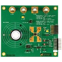
SPIO-4/NOPB National Semiconductor, SPIO-4/NOPB Datasheet - Page 11

SPIO-4/NOPB
Manufacturer Part Number
SPIO-4/NOPB
Description
BOARD INTERFACE FOR AFE
Manufacturer
National Semiconductor
Datasheet
1.SPIO-4NOPB.pdf
(26 pages)
Specifications of SPIO-4/NOPB
Main Purpose
Interface, Analog Front End (AFE)
Embedded
Yes, MCU, 32-Bit
Utilized Ic / Part
SAM3U, XC6SLX16
Primary Attributes
USB Powered or External Supply
Secondary Attributes
GUI, I2C, SPI, USB Interfaces
Accessory Type
Digital Interface Board
Msl
MSL 1 - Unlimited
Lead Free Status / RoHS Status
Lead free / RoHS Compliant
Other names
SPI0-4/NOPB
SPI0-4/NOPB
SPI0-4/NOPB
Available stocks
Company
Part Number
Manufacturer
Quantity
Price
Company:
Part Number:
SPIO-4/NOPB
Manufacturer:
National Semiconductor
Quantity:
135
National Semiconductor
15
16
17
18
19
20
21
22
23
24
25
26
27
the DUT board must leave this pin open. Maximum capacitor loading
for this node is not to exceed 50uF.
VDDIO
Interface Supply always provided by the DUT board. Both the DUT
board and the SPIO-4 board power their I/O drivers with this supply
(except the I2C bus – which is always +3.3V). Only the SPI_A related
signals on the GPSI-16 subset are affected by this I/O supply. Voltage
Range: 1.6V to 5.5V. Capable of supplying 100mA.
SCS2_A~
SerialBus A – Chip Select for device 2.
DUT_PWR_Enable
For those DUT boards that support intelligent power-up control, this
signal from the SPIO-4 enables the DUT power regulators.
Available for implementation specific use. Refer to the DUT
board manual.
Available for implementation specific use. Refer to the DUT
board manual.
Available for implementation specific use. Refer to the DUT
board manual.
Available for implementation specific use. Refer to the DUT
board manual.
Available for implementation specific use. Refer to the DUT
board manual.
Available for implementation specific use. Refer to the DUT
board manual.
If a second SPI bus is implemented, then use this pin as shown:
SCS0_B~
SerialBus B – Chip Select for device 0.
Available for implementation specific use. Refer to the DUT
board manual.
If a second SPI bus is implemented, then use this pin as shown:
SDRDY_B~
In certain SPI applications, if required, this pin serves as the DRDY~
signal from the DUT to the SPIO-4.
Available for implementation specific use. Refer to the DUT
board manual.
If a second SPI bus is implemented, then use this pin as shown:
SCK_B
Serial Bus B – Serial Clock from the master to the device.
Available for implementation specific use. Refer to the DUT
board manual.
If a second SPI bus is implemented, then use this pin as shown:
SCS1_B~
SerialBus B – Chip Select for device 1.
Available for implementation specific use. Refer to the DUT
board manual.
If a second SPI bus is implemented, then use this pin as shown:
SMISO_B
If unused, leave it open. (Possible use: DUT_RESET~)
If unused, leave it open.
If unused, leave it open.
If unused, leave it open.
If unused, leave it open.
If unused, leave it open.
If unused, leave it open.
If unused, leave it open.
If unused, leave it open.
If unused, leave it open.
Page 11
1.65 to
1.65 to
5.5V
5.5V
3.3V
3.3V
3.3V
3.3V
3.3V
3.3V
3.3V
3.3V
3.3V
3.3V
3.3V
INPUT
OUTPUT
OUTPUT
www.national.com


