NUMICRO-SDK Nuvoton Technology Corporation of America, NUMICRO-SDK Datasheet - Page 357
NUMICRO-SDK
Manufacturer Part Number
NUMICRO-SDK
Description
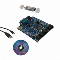
KIT EVAUATION NUC100/120/130/140
Manufacturer
Nuvoton Technology Corporation of America
Series
NuMicro™r
Type
MCUr
Datasheets
1.NUC100LC1BN.pdf
(600 pages)
2.NUMICRO-SDK.pdf
(13 pages)
3.NUMICRO-SDK.pdf
(93 pages)
4.NUMICRO-SDK.pdf
(1 pages)
Specifications of NUMICRO-SDK
Contents
Board, Cable, CD, Nu-Link
Lead Free Status / RoHS Status
Lead free / RoHS Compliant
For Use With/related Products
NUC100, NUC120, NUC130, NUC140
Available stocks
Company
Part Number
Manufacturer
Quantity
Price
Company:

Part Number:
NUMICRO-SDK
Manufacturer:
Nuvoton Technology Corporation
Quantity:
135
Company:
Part Number:
NUMICRO-SDK
Manufacturer:
NuvoTon
Quantity:
69


[18]
[17]
[16]
[15:12]
[11]
[10]
[9:8]
[7:3]
NuMicro™ NUC100 Series Technical Reference Manual
SLAVE
IE
IF
SP_CYCLE
CLKP
LSB
TX_NUM
TX_BIT_LEN
Byte reorder function is only available if TX_BIT_LEN is defined as 16, 24,
and 32 bits.
Slave Mode Indication
1 = Slave mode
0 = Master mode
Interrupt Enable
1 = Enable SPI/MICROWIRE Interrupt
0 = Disable SPI/MICROWIRE Interrupt
Interrupt Flag
1 = It indicates that the transfer is done. The interrupt flag is set if it was enable.
0 = It indicates that the transfer dose not finish yet.
Note: This bit is cleared by writing 1 to itself.
Suspend Interval (Master Only)
These four bits provide configurable suspend interval between two successive
transmit/receive transaction in a transfer. The suspend interval is from the last falling
clock edge of the current transaction to the first rising clock edge of the successive
transaction if CLKP = 0. If CLKP = 1, the interval is from the rising clock edge to the
falling clock edge. The default value is 0x0. When TX_NUM = 00b, setting this field has
no effect on transfer. The desired suspend interval is obtained according to the
following equation:
(SP_CYCLE[3:0] + 2) * period of SPICLK
SP_CYCLE = 0x0 … 2 SPICLK clock cycle
SP_CYCLE = 0x1 … 3 SPICLK clock cycle
……
SP_CYCLE = 0xE … 16 SPICLK clock cycle
SP_CYCLE = 0xF … 17 SPICLK clock cycle
Clock Polarity
1 = SPICLK idle high
0 = SPICLK idle low
LSB First
1 = The LSB is sent first on the line (bit 0 of SPI_TX0/1), and the first bit received from
0 = The MSB is transmitted/received first (which bit in SPI_TX0/1 and SPI_RX0/1
Numbers of Transmit/Receive Word
This field specifies how many transmit/receive word numbers should be executed in
one transfer.
00 = Only one transmit/receive word will be executed in one transfer.
01 = Two successive transmit/receive words will be executed in one transfer. (burst
10 = Reserved.
11 = Reserved.
Transmit Bit Length
This field specifies how many bits are transmitted in one transaction. Up to 32 bits can
be transmitted.
the line will be put in the LSB position in the RX register (bit 0 of SPI_RX0/1).
register that is depends on the TX_BIT_LEN field).
mode)
- 357 -
Publication Release Date: Oct 22, 2010
Revision V1.06
Related parts for NUMICRO-SDK
Image
Part Number
Description
Manufacturer
Datasheet
Request
R

Part Number:
Description:
IC MCU 32BIT 32KB FLASH 33QFN
Manufacturer:
Nuvoton Technology Corporation of America
Datasheet:
Part Number:
Description:
IC MCU 32BIT 32KB FLASH 48LQFP
Manufacturer:
Nuvoton Technology Corporation of America
Datasheet:

Part Number:
Description:
IC MCU 32BIT 32KB FLASH 48LQFP
Manufacturer:
Nuvoton Technology Corporation of America
Datasheet:

Part Number:
Description:
IC MCU 32BIT 64KB FLASH 33QFN
Manufacturer:
Nuvoton Technology Corporation of America
Datasheet:

Part Number:
Description:
IC MCU 32BIT 32KB FLASH 48LQFP
Manufacturer:
Nuvoton Technology Corporation of America
Datasheet:

Part Number:
Description:
IC MCU 32BIT 64KB FLASH 48LQFP
Manufacturer:
Nuvoton Technology Corporation of America
Datasheet:

Part Number:
Description:
IC MCU 32BIT 64KB FLASH 64LQFP
Manufacturer:
Nuvoton Technology Corporation of America
Datasheet:

Part Number:
Description:
IC MCU 32BIT 64KB FLASH 64LQFP
Manufacturer:
Nuvoton Technology Corporation of America
Datasheet:

Part Number:
Description:
IC MCU 32BIT 64KB FLASH 48LQFP
Manufacturer:
Nuvoton Technology Corporation of America
Datasheet:
Part Number:
Description:
IC MCU 32BIT 64KB FLASH 64LQFP
Manufacturer:
Nuvoton Technology Corporation of America
Datasheet:

Part Number:
Description:
IC MCU 32BIT 8KB FLASH 33QFN
Manufacturer:
Nuvoton Technology Corporation of America
Datasheet:

Part Number:
Description:
IC MCU 32BIT 8KB FLASH 48LQFP
Manufacturer:
Nuvoton Technology Corporation of America
Datasheet:
Part Number:
Description:
IC MCU 32BIT 16KB FLASH 33QFN
Manufacturer:
Nuvoton Technology Corporation of America
Datasheet:
Part Number:
Description:
IC MCU 32BIT 64KB FLASH 100LQFP
Manufacturer:
Nuvoton Technology Corporation of America
Datasheet:

Part Number:
Description:
IC MCU 32BIT 128KB FLASH 64LQFP
Manufacturer:
Nuvoton Technology Corporation of America
Datasheet: