MCIMX53-START Freescale Semiconductor, MCIMX53-START Datasheet - Page 73
MCIMX53-START
Manufacturer Part Number
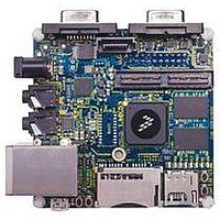
MCIMX53-START
Description
KIT DEVELOPMENT I.MX53
Manufacturer
Freescale Semiconductor
Series
i.MX53r
Type
MCUr
Datasheets
1.MCIMX53-START.pdf
(2 pages)
2.MCIMX53-START.pdf
(180 pages)
3.MCIMX53-START.pdf
(204 pages)
Specifications of MCIMX53-START
Contents
Board
Silicon Manufacturer
Freescale
Core Architecture
ARM
Core Sub-architecture
Cortex - A8
Silicon Core Number
I.MX5
Silicon Family Name
I.MX53
Peak Reflow Compatible (260 C)
Yes
Rohs Compliant
Yes
Leaded Process Compatible
Yes
Lead Free Status / RoHS Status
Lead free / RoHS Compliant
For Use With/related Products
i.MX53
Lead Free Status / Rohs Status
Supplier Unconfirmed
Available stocks
Company
Part Number
Manufacturer
Quantity
Price


4.7.4.2
Figure 35
that only DATA is sampled on both edges of the clock (not applicable to CMD).
Freescale Semiconductor
1
2
3
4
To satisfy hold timing, the delay difference between clock input and cmd/data input must not exceed 2 ns.
SD7
SD8
In low speed mode, card clock must be lower than 400 kHz, voltage ranges from 2.7 to 3.6 V.
In normal (full) speed mode for SD/SDIO card, clock frequency can be any value between 0
clock frequency can be any value between 0
In normal (full) speed mode for MMC card, clock frequency can be any value between 0
frequency can be any value between 0
SD1
SD2
ID
ID
eSDHC Input Setup Time
eSDHC Input Hold Time
Clock Frequency (MMC Full Speed/High Speed)
eSDHC Output Delay
output from eSDHCv3 to card
input from card to eSDHCv3
depicts the timing of eMMC4.4.
eMMC4.4 (Dual Data Rate) eSDHCv3 AC Timing
Table 46. SD/eMMC4.3 Interface Timing Specification (continued)
i.MX53xD Applications Processors for Consumer Products, Rev. 1
eSDHC Output / Card Inputs CMD, DAT (Reference to CLK)
eSDHC Input / Card Outputs CMD, DAT (Reference to CLK)
Parameter
Table 47. eMMC4.4 Interface Timing Specification
4
Parameter
DAT0
......
DAT7
DAT1
DAT0
......
DAT7
SCK
DAT1
–
52 MHz.
–
Figure 35. eMMC4.4 Timing
50 MHz.
Table 47
Card Input Clock
SD2
lists the eMMC4.4 timing characteristics. Be aware
SD3
Symbols
SD4
t
f
OD
PP
Symbols
t
ISU
t
IH
SD2
SD1
–
Min
–5
20 MHz. In high-speed mode, clock
0
Min
2.5
2.5
–
25 MHz. In high-speed mode,
Electrical Characteristics
Max
52
5
Max
......
—
—
......
MHz
Unit
Unit
ns
ns
ns
73
Related parts for MCIMX53-START
Image
Part Number
Description
Manufacturer
Datasheet
Request
R

Part Number:
Description:
MCIMX-LVDS1
Manufacturer:
Freescale Semiconductor
Datasheet:

Part Number:
Description:
Manufacturer:
Freescale Semiconductor, Inc
Datasheet:
Part Number:
Description:
Manufacturer:
Freescale Semiconductor, Inc
Datasheet:
Part Number:
Description:
Manufacturer:
Freescale Semiconductor, Inc
Datasheet:
Part Number:
Description:
Manufacturer:
Freescale Semiconductor, Inc
Datasheet:
Part Number:
Description:
Manufacturer:
Freescale Semiconductor, Inc
Datasheet:
Part Number:
Description:
Manufacturer:
Freescale Semiconductor, Inc
Datasheet:
Part Number:
Description:
Manufacturer:
Freescale Semiconductor, Inc
Datasheet:
Part Number:
Description:
Manufacturer:
Freescale Semiconductor, Inc
Datasheet:
Part Number:
Description:
Manufacturer:
Freescale Semiconductor, Inc
Datasheet:
Part Number:
Description:
Manufacturer:
Freescale Semiconductor, Inc
Datasheet:
Part Number:
Description:
Manufacturer:
Freescale Semiconductor, Inc
Datasheet:
Part Number:
Description:
Manufacturer:
Freescale Semiconductor, Inc
Datasheet:
Part Number:
Description:
Manufacturer:
Freescale Semiconductor, Inc
Datasheet:
Part Number:
Description:
Manufacturer:
Freescale Semiconductor, Inc
Datasheet: