MCIMX53-START Freescale Semiconductor, MCIMX53-START Datasheet - Page 81
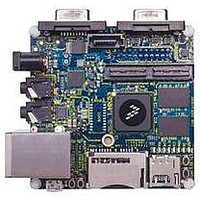
MCIMX53-START
Manufacturer Part Number
MCIMX53-START
Description
KIT DEVELOPMENT I.MX53
Manufacturer
Freescale Semiconductor
Series
i.MX53r
Type
MCUr
Datasheets
1.MCIMX53-START.pdf
(2 pages)
2.MCIMX53-START.pdf
(180 pages)
3.MCIMX53-START.pdf
(204 pages)
Specifications of MCIMX53-START
Contents
Board
Silicon Manufacturer
Freescale
Core Architecture
ARM
Core Sub-architecture
Cortex - A8
Silicon Core Number
I.MX5
Silicon Family Name
I.MX53
Peak Reflow Compatible (260 C)
Yes
Rohs Compliant
Yes
Leaded Process Compatible
Yes
Lead Free Status / RoHS Status
Lead free / RoHS Compliant
For Use With/related Products
i.MX53
Lead Free Status / Rohs Status
Supplier Unconfirmed
Available stocks
Company
Part Number
Manufacturer
Quantity
Price


2
3
4
5
6
7
4.7.8.2
There are three camera timing modes supported by the IPU.
4.7.8.2.1
Smart camera sensors, which include imaging processing, usually support video mode transfer. They use
an embedded timing syntax to replace the SENSB_VSYNC and SENSB_HSYNC signals. The timing
syntax is defined by the BT.656/BT.1120 standards.
This operation mode follows the recommendations of ITU BT.656/ ITU BT.1120 specifications. The only
control signal used is SENSB_PIX_CLK. Start-of-frame and active-line signals are embedded in the data
stream. An active line starts with a SAV code and ends with a EAV code. In some cases, digital blanking
is inserted in between EAV and SAV code. The CSI decodes and filters out the timing-coding from the data
stream, thus recovering SENSB_VSYNC and SENSB_HSYNC signals for internal use. On BT.656 one
component per cycle is received over the SENSB_DATA bus. On BT.1120 two components per cycle are
received over the SENSB_DATA bus.
4.7.8.2.2
The SENSB_VSYNC, SENSB_HSYNC, and SENSB_PIX_CLK signals are used in this mode. See
Figure
A frame starts with a rising edge on SENSB_VSYNC (all the timings correspond to straight polarity of the
corresponding signals). Then SENSB_HSYNC goes to high and hold for the entire line. Pixel clock is
valid as long as SENSB_HSYNC is high. Data is latched at the rising edge of the valid pixel clocks.
Freescale Semiconductor
The MSB bits are duplicated on LSB bits implementing color extension
The two MSB bits are duplicated on LSB bits implementing color extension
RGB 16 bits – supported in two ways: (1) As a “generic data” input – with no on-the-fly processing; (2) With on-the-fly
processing, but only under some restrictions on the control protocol.
YCbCr 16 bits - supported as a “generic-data” input – with no on-the-fly processing.
YCbCr 16 bits - supported as a sub-case of the YCbCr, 20 bits, under the same conditions (BT.1120 protocol).
YCbCr, 20 bits, supported only within the BT.1120 protocol (syncs embedded within the data stream).
42.
SENSB_DATA[19:0]
SENSB_PIX_CLK
SENSB_HSYNC
SENSB_VSYNC
Sensor Interface Timings
BT.656 and BT.1120 Video Mode
Gated Clock Mode
Start of Frame
i.MX53xD Applications Processors for Consumer Products, Rev. 1
invalid
nth frame
Figure 42. Gated Clock Mode Timing Diagram
1st byte
Active Line
n+1th frame
invalid
1st byte
Electrical Characteristics
81
Related parts for MCIMX53-START
Image
Part Number
Description
Manufacturer
Datasheet
Request
R

Part Number:
Description:
MCIMX-LVDS1
Manufacturer:
Freescale Semiconductor
Datasheet:

Part Number:
Description:
Manufacturer:
Freescale Semiconductor, Inc
Datasheet:
Part Number:
Description:
Manufacturer:
Freescale Semiconductor, Inc
Datasheet:
Part Number:
Description:
Manufacturer:
Freescale Semiconductor, Inc
Datasheet:
Part Number:
Description:
Manufacturer:
Freescale Semiconductor, Inc
Datasheet:
Part Number:
Description:
Manufacturer:
Freescale Semiconductor, Inc
Datasheet:
Part Number:
Description:
Manufacturer:
Freescale Semiconductor, Inc
Datasheet:
Part Number:
Description:
Manufacturer:
Freescale Semiconductor, Inc
Datasheet:
Part Number:
Description:
Manufacturer:
Freescale Semiconductor, Inc
Datasheet:
Part Number:
Description:
Manufacturer:
Freescale Semiconductor, Inc
Datasheet:
Part Number:
Description:
Manufacturer:
Freescale Semiconductor, Inc
Datasheet:
Part Number:
Description:
Manufacturer:
Freescale Semiconductor, Inc
Datasheet:
Part Number:
Description:
Manufacturer:
Freescale Semiconductor, Inc
Datasheet:
Part Number:
Description:
Manufacturer:
Freescale Semiconductor, Inc
Datasheet:
Part Number:
Description:
Manufacturer:
Freescale Semiconductor, Inc
Datasheet: