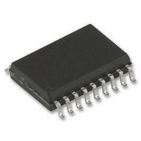
TMC222-SI TRINAMIC, TMC222-SI Datasheet - Page 21

TMC222-SI
Manufacturer Part Number
TMC222-SI
Description
IC, MOTOR CTRL/DRVR, STEPPER, SOIC-20
Manufacturer
TRINAMIC
Datasheet
1.TMC222-SI.pdf
(47 pages)
Specifications of TMC222-SI
Motor Type
Stepper
No. Of Outputs
4
Output Current
800mA
Supply Voltage Range
8V To 29V
Driver Case Style
SOIC
No. Of Pins
20
Operating Temperature Range
-40°C To +125°C
Device Type
Motor
Lead Free Status / RoHS Status
Lead free / RoHS Compliant
Available stocks
Company
Part Number
Manufacturer
Quantity
Price
Part Number:
TMC222-SI
Manufacturer:
TRINAMI
Quantity:
20 000
TMC222 DATASHEET (V. 1.06 / March 15, 2007)
5.2.3
The table below shows where the OTP parameters are stored in the OTP memory.
Note: If the OTP memory has not been programmed, or if the RAM has not be programmed by a
SetMotorParam command, or if anyhow <VddReset> = ‘1’, any positioning command will be ignored,
in order to avoid any consequence due to unwanted RAM content. Please check that the correct
supply voltage is applied to the circuit before zapping the OTP (See: Table 21: DC Parameters
Supply and Voltage regulator on page 45), otherwise the circuit will be destroyed.
Parameters stored at address 0x00 and 0x01 and bit LOCKBT are already programmed in the OTP
memory at circuit delivery, they correspond to the calibration of the circuit and are just documented
here as an indication. Each OPT bit is at ‘0’ when not zapped. Zapping a bit will set it to ‘1’. Thus only
bits having to be at ‘1’ must be zapped. Zapping of a bit already at ‘1’ is disabled, to avoid any
damage of the Zener diode. It is important to note that only one single OTP byte can be programmed
at the same time (see command SetOTPParam).
Once OTP programming is completed, bit LOCKBG can be zapped, to disable unwanted future
zapping, otherwise any OTP bit at ‘0’ could still be zapped.
The command used to load the application parameters via the serial bus into the RAM prior to an
OTP Memory programming is SetMotorParam. This allows for a functional verification before using a
SetOTPParam command to program and zap separately one OTP memory byte. A GetOTPParam
command issued after each SetOTPParam command allows to verify the correct byte zapping.
5.3 Stepper Motor Driver
The StepMode parameter in SetMotorParam command (6.8.9 SetMotorParam on page 34) is used to
select between different stepping modes. Following modes are available:
Copyright © 2004-2007 TRINAMIC Motion Control GmbH & Co. KG
Address
OTP
0x00
0x01
0x02
0x03
0x04
0x05
0x06
0x07
OTP Memory Structure
SecPos10.
SecPos7
Vmax3
OSC3
Irun3
7
LOCKBT
SecPos9
SecPos6
Vmax2
OSC2
TSD2
Irun2
6
StepMode parameter
(zapped before delivery)
LOCKBG
Lock bit
Table 9: OTP Memory Structure
SecPos8
SecPos5
Vmax1
OSC1
TSD1
Irun1
00
01
10
11
Table 10: OTP Lock bits
5
Table 11: StepMode
SecPos4
Vmax0
OSC0
TSD0
Irun0
Shaft
OTP Bit Order
4
StepMode1
1/16 µStepping
SecPos3
1/4 µStepping
1/8 µStepping
Half Stepping
Vmin3
IREF3
Ihold3
Acc3
BG3
AD3
3
Mode
Protected byte
0x00 to 0x01
0x02 to 0x07
StepMode0
SecPos2
IREF2
Vmin2
Ihold2
Acc2
BG2
AD2
2
SecPos1
LOCKBT
Vmin1
IREF1
Ihold1
Acc1
BG1
AD1
1
LOCKBG
SecPos0
Vmin0
IREF0
Ihold0
Acc0
BG0
AD0
0
21


