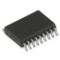
TMC222-SI TRINAMIC, TMC222-SI Datasheet - Page 28

TMC222-SI
Manufacturer Part Number
TMC222-SI
Description
IC, MOTOR CTRL/DRVR, STEPPER, SOIC-20
Manufacturer
TRINAMIC
Datasheet
1.TMC222-SI.pdf
(47 pages)
Specifications of TMC222-SI
Motor Type
Stepper
No. Of Outputs
4
Output Current
800mA
Supply Voltage Range
8V To 29V
Driver Case Style
SOIC
No. Of Pins
20
Operating Temperature Range
-40°C To +125°C
Device Type
Motor
Lead Free Status / RoHS Status
Lead free / RoHS Compliant
Available stocks
Company
Part Number
Manufacturer
Quantity
Price
Part Number:
TMC222-SI
Manufacturer:
TRINAMI
Quantity:
20 000
28
6.6 Timing characteristics of the serial interface
Parameter
Low level input voltage:
Fixed input levels
High level input voltage:
Fixed input levels
Pulse width of spikes which must be
suppressed by the input filter
Capacitance for each I/O pin
Notes
(1): If Input voltage = < -0.3 Volts, then 20…100 Ohms resistor must be added in series
(2): Maximum V
n/a: not applicable
SCL clock frequency
Hold time (repeated) START
condition. After this period, the first
clock pulse is generated.
LOW period of the SCL clock
HIGH period of the SCL clock
Set-up time for a repeated START
condition
Data set-up time
Rise time of both SDA and SCL
signals
Fall time of both SDA and SCL
signals
Set-up time for STOP condition
Bus free time between a STOP and
START condition
Capacitive load for each bus line
Noise margin at the LOW level for
each connected device (including
hysteresis)
Noise margin at the HIGH level for
each connected device (including
hysteresis)
Notes
(1): C
Copyright © 2004-2007 TRINAMIC Motion Control GmbH & Co. KG
SDA
SCL
b
= total capacitance of one bus line in pF.
Table 13: Two Wire Serial Interface - Characteristics of the SDA and SCL I/O Stages
Table 14: Two Wire Serial Interface - Characteristics of the SDA and SCL bus lines
t
f
Parameter
START
IH
= V
t
HD;STA
DDmax
t
LOW
+ 0.5 Volt
t
r
Symbol
t
HD;DAT
t
t
t
t
SU;STO
HD;STA
SU;STA
SU;DAT
t
Symbol
t
f
t
V
V
HIGH
LOW
C
SCL
BUF
t
t
t
nH
nL
r
f
SU;DAT
b
V
V
t
C
Figure 21: Definition of Timing
SP
IH
IL
i
t
HIGH
SCL Clk frequency <= 100KHz
t
f
SCL Clk frequency <= 100KHz
0.1V
0.2V
Min.
250
4.0
4.7
4.0
4.7
4.0
4.7
-0.5
0
0
-
-
Min.
3.0
n/a
DD
DD
-
(1)
t
SU;STA
TMC222 DATASHEET (V. 1.06 / March 15, 2007)
START
Max.
1000
100
300
400
Max.
-
-
-
-
-
-
-
-
-
t
1.5
n/a
10
HD;STA
(2)
SCL Clk frequency <= 350KHz
20+0.1C
20+0.1C
SCL Clk frequency <= 350KHz
0.1V
0.2V
Min.
100
0.6
1.3
0.6
0.6
0.6
1.3
0.7V
-0.5
0
Min.
-
50
DD
DD
-
b
b
(1)
DD
(1)
(1)
t
SU;STO
t
r
STOP
Max.
350
300
300
400
0.3V
Max.
-
-
-
-
-
-
-
-
-
50
10
(2)
t
DD
BUF
START
Unit
KHz
µs
µs
µs
µs
µs
µs
pF
Unit
ns
ns
ns
V
V
pF
ns
V
V


