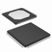
XC2C384-10TQG144C Xilinx Inc, XC2C384-10TQG144C Datasheet - Page 13

XC2C384-10TQG144C
Manufacturer Part Number
XC2C384-10TQG144C
Description
IC, CPLD, 384 MACROCELL, 7.1NS, TQFP-144
Manufacturer
Xilinx Inc
Series
CoolRunner IIr
Specifications of XC2C384-10TQG144C
No. Of Macrocells
384
No. Of I/o's
118
Propagation Delay
7.1ns
Global Clock Setup Time
3.3ns
Frequency
125MHz
Supply Voltage Range
1.7V To 1.9V
Programmable Type
In System Programmable
Delay Time Tpd(1) Max
9.2ns
Voltage Supply - Internal
1.7 V ~ 1.9 V
Number Of Logic Elements/blocks
24
Number Of Macrocells
384
Number Of Gates
9000
Number Of I /o
118
Operating Temperature
0°C ~ 70°C
Mounting Type
Surface Mount
Package / Case
144-TQFP, 144-VQFP
Features
JTAG
Voltage
1.8V
Memory Type
CMOS
Rohs Compliant
Yes
Lead Free Status / RoHS Status
Lead free / RoHS Compliant
Number Of Logic Elements/cells
-
Lead Free Status / RoHS Status
Lead free / RoHS Compliant, Lead free / RoHS Compliant
Other names
122-1406
Available stocks
Company
Part Number
Manufacturer
Quantity
Price
Company:
Part Number:
XC2C384-10TQG144C
Manufacturer:
XILINX
Quantity:
214
Company:
Part Number:
XC2C384-10TQG144C
Manufacturer:
XILINX
Quantity:
455
Company:
Part Number:
XC2C384-10TQG144C
Manufacturer:
Xilinx Inc
Quantity:
10 000
to be programmed at any time. All devices are shipped in
the erased state from the factory.
Applying power to a blank part might result in a higher cur-
rent flow as the part initializes. This behavior is normal and
might persist for approximately 2 seconds, depending on
the power supply ramp.
If the device is programmed, the device inputs and outputs
take on their configured states for normal operation. The
JTAG pins are enabled to allow device erasure or bound-
ary-scan tests at any time.
Table 8: I/O Power-Up Characteristics
I/O Banking
CoolRunner-II CPLD XC2C32A and XC2C64A macrocell
parts support two V
down to 1.5V operation. Two V
the 128 and 256 macrocell parts where outputs on each rail
can independently range from 3.3V down to 1.5V operation.
Four V
cell parts. Any of the V
V
assign input and output voltages to a bank with V
the voltage range of that input or output voltage. The V
(internal supply voltage) for a CoolRunner-II CPLD must be
maintained within 1.8V ±5% for correct speed operation and
proper in system programming.
Mixed Voltage, Power Sequencing, and
Hot Plugging
As mentioned in I/O Banking, CoolRunner-II CPLD parts
support mixed voltage I/O signals. It is important to assign
signals to an I/O bank with the appropriate I/O voltage. Driv-
ing a high voltage into a low voltage bank can result in neg-
ative current flow through the power supply pins. The power
applied to the V
DS090 (v3.1) September 11, 2008
Product Specification
IOB Bus-Hold/Weak Pullup
Device Outputs
Device Inputs and Clocks
Function Block
JTAG Controller
CCIO
values of 1.5V, 1.8V, 2.5V, or 3.3V. Designers should
Device Circuitry
CCIO
rails are supported on the 384 and 512 macro-
R
CCIO
CCIO
and V
CCIO
rails that can range from 3.3V
rails can assume any one of the
CC
pins can occur in any order
CCIO
Quiescent State
rails are supported on
Weak Pull-up
Disabled
Disabled
Disabled
Disabled
CCIO
www.xilinx.com
set at
CC
Erased Device Operation
and the CoolRunner-II CPLD will not be damaged. For best
results, Xilinx recommends that V
V
I/Os are active. CoolRunner-II CPLDs can reside on boards
where the board is inserted into a “live” connector (hot
plugged) and the parts will be well-behaved as if powering
up in a standard way.
Development System Support
Xilinx CoolRunner-II CPLDs are supported by all configura-
tions of Xilinx standard release development software as
well as the freely available ISE WebPACK software avail-
able from www.xilinx.com. Third party development tools
include synthesis tools from Cadence, Exemplar, Mentor
Graphics, Synplicity, and Synopsys.
ATE Support
Third party ATE development support is available for both
programming and board/chip level testing. Vendors provid-
ing this support include Agilent, GenRad, and Teradyne.
Other third party providers are expected to deliver solutions
in the future.
CCIO
3.8 V
(Typ)
1.3V
(Typ)
0V
Weak Pull-up
Figure 12: Device Behavior During Power Up
Power
V
To ensure that the internal logic is correct before the
CCINT
No
Disabled
Disabled
Disabled
Enabled
Quiescent
State
Initialization Transition of User Array
User Operation
CoolRunner-II CPLD Family
Bus-Hold/Weak Pullup
Valid User Operation
CCINT
As Configured
As Configured
As Configured
Enabled
be applied before
Quiescent
State
Power
x382_10
No
13


