AD532SD Analog Devices Inc, AD532SD Datasheet - Page 6
AD532SD
Manufacturer Part Number
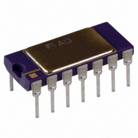
AD532SD
Description
Multiplexer IC
Manufacturer
Analog Devices Inc
Specifications of AD532SD
Ic Function
Analog Multiplier/Divider IC
Package/case
14-CDIP
Accuracy
1 %
Leaded Process Compatible
No
Number Of Channels
4
Output Voltage
13V
Peak Reflow Compatible (260 C)
No
Supply Voltage Max
18V
Rohs Status
RoHS non-compliant
Function
Analog Multiplier/Divider
Number Of Bits/stages
4-Quadrant
Package / Case
14-CDIP (0.300", 7.62mm)
Lead Free Status / RoHS Status
Contains lead / RoHS non-compliant
Available stocks
Company
Part Number
Manufacturer
Quantity
Price

Company:
Part Number:
AD532SD/883B
Manufacturer:
ADI
Quantity:
676


AD532
APPLICATIONS
MULTIPLICATION
For operation as a multiplier, the AD532 should be connected
as shown in Figure 11. The inputs can be fed differentially to
the X and Y inputs, or single-ended by simply grounding the
unused input. Connect the inputs according to the desired po-
larity in the output. The Z terminal is tied to the output to close
the feedback loop around the op amp (see Figure 1). The offset
adjust V
volts to obtain zero out, or to buck out other system offsets.
SQUARE
The squaring circuit in Figure 12 is a simple variation of the
multiplier. The differential input capability of the AD532, how-
ever, can be used to obtain a positive or negative output re-
sponse to the input . . . a useful feature for control applications,
as it might eliminate the need for an additional inverter somewhere
else.
DIVISION
The AD532 can be configured as a two-quadrant divider by
connecting the multiplier cell in the feedback loop of the op
amp and using the Z terminal as a signal input, as shown in
Figure 13. It should be noted, however, that the output error is
given approximately by 10 V
error specification for the multiply mode; and bandwidth by
f
Further, to avoid positive feedback, the X input is restricted to
negative values. Thus for single-ended negative inputs (0 V to
–10 V), connect the input to X and the offset null to X
m
(X
1
OS
– X
X
X
Y
Y
(OPTIONAL)
2.2k
2
2
is optional and is adjusted when both inputs are zero
1
1
2
)/10 V, where f
V
Figure 11. Multiplier Connection
IN
Figure 12. Squarer Connection
Figure 13. Divider Connection
Z
X
X
Y
X
Y
+V
1
2
1
2
47k
S
AD532
+V
+V
20k
V
S
AD532
S
OS
X
X
Y
Y
20k
V
2
2
1
1
OS
–V
+V
+V
m
S
S
S
Z
–V
AD532
–V
is the bandwidth of the multiplier.
20k
m
OUT
S
(X
Z
S
/(X
0
OUT
)
(OPTIONAL)
–V
–V
V
1
OUT
– X
Z
S
S
OUT
=
2
(X
), where
V
V
OUT
1
OUT
V
– X
V
OUT
OUT
= 10VZ
2
10V
10k
1k
(SF)
) (Y
=
V
X
10V
1
V
IN
– Y
OUT
2
m
2
is the total
)
2
; for
–6–
single-ended positive inputs (0 V to +10 V), connect the input
to X
(S.F.) and offset (X
and explained in Table I.
For practical reasons, the useful range in denominator input is
approximately 500 mV
adjust (V
full scale.
Adjust
Scale Factor
X
Repeat if required.
SQUARE ROOT
The connections for square root mode are shown in Figure 14.
Similar to the divide mode, the multiplier cell is connected in
the feedback of the op amp by connecting the output back to
both the X and Y inputs. The diode D
to prevent latch-up as Z
V
obtain –1.0 V dc in the output, V
performance, gain (S.F.) and offset (X
mended as shown and explained in Table I.
DIFFERENCE OF SQUARES
The differential input capability of the AD532 allows for the
algebraic solution of several interesting functions, such as the
difference of squares, X
AD532 is configured in the square mode, with a simple unity
gain inverter connected between one of the signal inputs (Y)
and one of the inverting input terminals (–Y
The inverter should use precision (0.1%) resistors or be other-
wise trimmed for unity gain for best accuracy.
OS
0
(Offset)
Table I. Adjust Procedure (Divider or Square Rooter)
2
adjustment is made with Z
and the offset null to X
X
Y
Figure 15. Differential of Squares Connection
OS
2.2k
), if used, is trimmed with Z at zero and (X
Figure 14. Square Rooter Connection
20k
10k
X
–10 V +10 V
–1 V
With:
Z
47k
DIVIDER
0
20k
) adjustments are recommended as shown
AD741KH
Z
+0.1 V –1 V
X
X
Y
Y
2
IN
1
2
1
2
– Y
|(X
+V
–Y
+V
approaches 0 volts. In this case, the
S
S
AD532
2
X
X
Y
Y
1
1
/10 V. As shown in Figure 15, the
20k
2
2
. For optimum performance, gain
(X
1
1
– X
IN
+V
+V
0
Adjust
for:
V
–10 V
)
S
OUT
= +0.1 V dc, adjusting V
AD532
S
OUT
2
–V
–V
20k
)|
V
Z
S
S
OS
OUT
= – 10 V Z. For optimum
1
0
–V
–V
) adjustments are recom-
10 V. The voltage offset
is connected as shown
S
S
V
Z
(OPTIONAL)
SQUARE ROOTER
OUT
OUT
With:
Z
+10 V
+0.1 V
IN
= 10VZ
) of the multiplier.
V
10k
1k
(SF)
OUT
V
=
OUT
V
X
OUT
2
10V
– Y
1
for:
V
–10 V
Adjust
–1 V
– X
OUT
2
REV. B
OS
2
) at
to
Related parts for AD532SD
Image
Part Number
Description
Manufacturer
Datasheet
Request
R

Part Number:
Description:
±1.7g Dual-Axis IMEMS Accelerometer Evaluation Board
Manufacturer:
Analog Devices Inc
Datasheet:

Part Number:
Description:
Inertial Sensor Evaluation System
Manufacturer:
Analog Devices Inc
Datasheet:
Part Number:
Description:
Manufacturer:
Analog Devices Inc
Datasheet:
Part Number:
Description:
Manufacturer:
Analog Devices Inc
Datasheet:
Part Number:
Description:
Manufacturer:
Analog Devices Inc
Datasheet:
Part Number:
Description:
Manufacturer:
Analog Devices Inc
Datasheet:
Part Number:
Description:
Manufacturer:
Analog Devices Inc
Datasheet:
Part Number:
Description:
Manufacturer:
Analog Devices Inc
Datasheet:
Part Number:
Description:
Manufacturer:
Analog Devices Inc
Datasheet:
Part Number:
Description:
Manufacturer:
Analog Devices Inc
Datasheet:
Part Number:
Description:
Manufacturer:
Analog Devices Inc
Datasheet:
Part Number:
Description:
Manufacturer:
Analog Devices Inc
Datasheet:
Part Number:
Description:
Manufacturer:
Analog Devices Inc
Datasheet: