3UG4622-1AW30 SIEMENS, 3UG4622-1AW30 Datasheet - Page 80
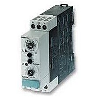
3UG4622-1AW30
Manufacturer Part Number
3UG4622-1AW30
Description
RELAY, MONITOR, 22.5MM
Manufacturer
SIEMENS
Series
3UG46r
Datasheet
1.3UG4622-1AW30.pdf
(114 pages)
Specifications of 3UG4622-1AW30
Contact Configuration
SPCO
Power Consumption
4VA
Supply Voltage Max
240VAC
Contact Current Max
3A
Relay Mounting
DIN Rail
Coil Voltage Vac Nom
230V
External Depth
86mm
Coil Frequency Max
60Hz
Coil Operating Frequency Min
50Hz


■
■
3UG Monitoring Relays for Electrical and Additional Measurements
Insulation monitoring
for ungrounded DC networks
Overview
Relay for monitoring the insulation resistance between
ungrounded pure DC networks and a protective-ground
conductor:
• Measuring principle for differential current measurement
• Response threshold can be set continuously from
• Selectable
Function
The monitoring relay measures the insulation voltage between
the positive and negative supply voltage in an ungrounded DC
network and a corresponding protective conductor.
The measurement is based on the DC residual current
measurement principle. The response value can be adjusted
steplessly in the range from 10 to 110 kW and thus can be
adapted to the corresponding conditions. If the insulation
resistance falls below the set response value, the output relay
triggers (depending on the setting of the open/closed-circuit
principle selector switch) and a fault LED lights up.
A ground fault is evaluated separately for L+ and L- and
indicated by means of a corresponding LED.
Note:
Due to the measurement principle, a symmetrical ground fault on
terminals L+ and L- cannot be evaluated.
Test function
A ground fault can be simulated using the Test L+ and Test L-
buttons on the front. If the test button is pressed for at least 1 s,
the status of the output relay changes and the corresponding
fault LED lights up.
An external test button can be connected to terminals Y1-Y3 for
L+ and terminals Y4-Y3 for L-. The function is triggered by
means of a NO contact.
Fault storage and RESET
If terminals Y2 and Y3 are linked, the monitoring relay is set to
fault storage mode.
If the insulation resistance falls below the set value, the output
relay triggers (depending on the setting of the open/closed
circuit selector switch), and stays in this state even if the
insulation resistance rises again above the hysteresis value
(typical: 2 times the set value). This fault storage can be deleted
by pressing and releasing the L+ RESET button, opening the
Y2-Y3 connection or by switching off the supply voltage.
7/80
10 to 110 kW
- Auto reset function with hysteresis or
- Storage of the tripping operation
Monitoring Relays
Siemens LV 1 T · 2006
• Front selector switch for open-circuit and closed-circuit
• Test function with test buttons on the front for L+ and L-
• Switching output: 1 CO contact
• Insulation fault indicator for L+ and L- through two red LEDs
• Supply voltage indication with a green LED
• Electro-magnetically compatible according to EN 50081 and
Open/closed-circuit principle selector switch
The function principle of the output relay can be adjusted by
means of a selector switch on the front panel.
If the relay is to respond in the event of a fault (contact symbol
open), the open-circuit principle must be selected. If the relay
however is to trigger in the event of a fault (contact symbol
closed), the closed-circuit principle must be selected.
Note:
The position of the selector switch has no effect upon the fault
LEDs. The LEDs always light up if the insulation resistance on L+
or L– falls below the set value.
principle for the output relay
and over terminal connections
EN 61000-6-2
Related parts for 3UG4622-1AW30
Image
Part Number
Description
Manufacturer
Datasheet
Request
R

Part Number:
Description:
RELAY, DIGITAL MONITORING, CURRENT
Manufacturer:
SIEMENS
Datasheet:

Part Number:
Description:
Intel 80C32 - Siemens SAB-C501, Nearest Equivalent Replacement
Manufacturer:
Siemens Semiconductor Group
Part Number:
Description:
IGBT MODULE
Manufacturer:
Siemens Semiconductor Group
Datasheet:
Part Number:
Description:
SIMOPAC Module (Power module Single switch N channel Enhancement mode)
Manufacturer:
Siemens Semiconductor Group
Datasheet:
Part Number:
Description:
(BSMxxx) TRANSISTOR
Manufacturer:
Siemens Semiconductor Group
Datasheet:
Part Number:
Description:
SIMOPAC Module (Power module Single switch N channel Enhancement mode)
Manufacturer:
Siemens Semiconductor Group
Datasheet:
Part Number:
Description:
main ratings
Manufacturer:
Siemens Semiconductor Group
Datasheet:
Part Number:
Description:
Manufacturer:
Siemens Semiconductor Group
Datasheet:
Part Number:
Description:
Manufacturer:
Siemens Semiconductor Group
Datasheet:
Part Number:
Description:
Manufacturer:
Siemens Semiconductor Group
Datasheet:
Part Number:
Description:
ICs for Consumer Electronics
Manufacturer:
Siemens Semiconductor Group
Datasheet:
Part Number:
Description:
Video and Sound IF with V & S SCART
Manufacturer:
Siemens Semiconductor Group
Datasheet:
Part Number:
Description:
Manufacturer:
Siemens Semiconductor Group
Datasheet:
Part Number:
Description:
Multistandard Sound IF
Manufacturer:
Siemens Semiconductor Group
Datasheet: