10250T3 EATON CUTLER HAMMER, 10250T3 Datasheet - Page 133
10250T3
Manufacturer Part Number
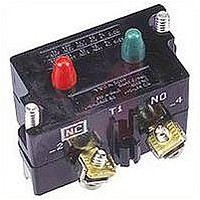
10250T3
Description
CONTACT BLOCK, 2NC, 6A, SCREW
Manufacturer
EATON CUTLER HAMMER
Datasheet
1.10250T101.pdf
(244 pages)
Specifications of 10250T3
No. Of Poles
2
Contact Current Max
6A
Contact Voltage Ac Max
600V
Contact Voltage Dc Max
250V
Switch Terminals
Screw
For Use With
10250T Series Pushbuttons And Indicating Lights
Lead Free Status / RoHS Status
Contains lead / RoHS non-compliant


March 2008
Selector Switch Selection
Cam and Contact Block Selection
Selector switches in their varied forms
(2-position, 3-position and 4-position)
are a big factor contributing to the
great flexibility of control that a well
rounded line of “pushbuttons” can
achieve. Because of their flexibility,
they tend to cause difficulty with prod-
uct selection and application. The
following systematic approach should
simplify that task.
Cam and contact block selection is
better understood if you:
■
■
■
■
Figure 47-94. Contact Circuit Locations
CA08102001E
Work with each incoming and out-
going wire/circuit separately.
Recognize the terms NO and NC
only identify the type of contact by
its mode before mounting to the
operator. The “X-O” table (Page 47-
134) shows how that contact will act
after assembly to the operator with
the selected cam shape. X = closed
circuit, O = open circuit.
Up to six NO or NC contacts may be
mounted behind each plunger loca-
tion for a total of twelve contacts.
Single circuit contact blocks have
only one plunger with the other side
of the block “open.” Therefore, single
circuit contact blocks transmit
motion to blocks behind them only
for the position containing the circuit.
Each cam has two separate lobes,
each of which operates one of the
two contact block plungers indepen-
dently of each other. Those are
identified as position A (locating nib
side) and position B (opposite of
locating nib). The position designa-
tions give direction in selecting and
mounting of the contact blocks (see
Figure 47-94).
10250T Series
Locating Nib
A
B
Systematic Approach
Application: HAND-OFF-AUTO Selector
Switch. In this circuit, one incoming
line is distributed to two other outgoing
circuits by the switch. The two circuits
can be looked at individually.
Step 1: Elementary Diagram.
Construct on paper, or in your mind, a
simple elementary diagram of the
switching scheme as follows:
Step 2: “X-O” Pattern.
From the elementary diagram, you can
construct an “X-O” diagram which
describes when the contacts are to be
closed (X) or open (O) in the various
positions of the switch. The “X-O” for
the HAND circuit looks like this:
In this circuit, you want a contact
closed on the left (HAND) but open in
the center and right.
For the AUTO circuit, the “X-O” diagram
would look like this:
Putting them together, the complete
“X-O” diagram is:
Once the “X-O” diagram has been
generated, the next step is to select the
cam and contact block, or blocks,
needed to perform the desired “X-O”
functions. The selection table on the
following page lists the various types
(shapes) of cams by number to choose
from and the type of contact and posi-
tion to achieve the function outlined in
your “X-O” diagram.
Step 3: Cam Selection.
The cam you select determines
the operation of all contact blocks
mounted to the operator. It is selected
on the basis that it provides the sim-
plest circuitry for the desired “X-O”
diagram. The selection tables of the
following page show all the “X-O”
combinations. For the purpose of this
example, the applicable portion of
those tables is shown in Table 47-204.
For more information visit: www.eaton.com
Incoming
Pushbuttons & Indicating Lights
30.5 mm Heavy-Duty Watertight/Oiltight
10250T Series, Components — Selector Switch Selection
Line
HAND OFF AUTO
HAND OFF AUTO
X O O
O O X
X O O
O O X
HAND
OFF
AUTO
Outgoing
Outgoing
Circuit
Circuit
Table 47-204. Example Selection Table
Now to make the cam selection, make
a simple worksheet such as:
It becomes immediately obvious that
cam 3 is the better choice for two rea-
sons, (1) the series combination can be
avoided making it simpler to wire, (2)
only two contacts are required, which
is less expensive than the three contacts
required by cam 2.
Step 4: Contact Block Selection.
Having selected the cam, contact block
selection is simply a matter of gather-
ing the A position and B position circuits
into pairs which make up the most con-
venient contact block arrangement. If
there is an imbalance in the number of
circuits under A or B, then single circuit
blocks must be selected for these leftover
circuits.
Back to the worksheet, having selected
cam 3 do this:
Step 5: Selector Switch Operator.
Lastly, you have to choose from the
many types of operators — knob and
lever in various colors or keyed. Also
what combinations of maintained and
spring return functions are required.
Selection of these operators can be
found on Page 47-135. For the above
example you may want a 3-position
maintained black knob, cam 3 —
Catalog Number 10250T1323.
The Complete Switch: 10250T1323 with
one 10250T2 or, for one composite
catalog number, 10250T21KB found
on Page 47-132.
No. “X-O”
1
4
Wired in series.
X O O
O O X
X O X
O O X
Pattern
X O O
O O X
ANO
Cam Code #2
Top
A
NO NC
(A)NO – (B)NC
Cam 2
Bottom
B
NO
(B)NO
BNO
Top
A
Cam Code #3
NO
10250T2
Cam 3
(A)NO
(B)NO
Bottom
B
NO
47-133
47
Related parts for 10250T3
Image
Part Number
Description
Manufacturer
Datasheet
Request
R

Part Number:
Description:
10250 STD. DUTY RECTANGULAR PB
Manufacturer:
EATON CUTLER HAMMER
Part Number:
Description:
10250 STD. DUTY RECTANGULAR PB
Manufacturer:
EATON CUTLER HAMMER
Part Number:
Description:
Handle Tie Bar For (2) - 1 Pole Type BR Breakers
Manufacturer:
EATON CUTLER HAMMER
Part Number:
Description:
Type CL Breaker 25A/1Pole 120/240V 10K-Classified 1" Ckt Bkr
Manufacturer:
EATON CUTLER HAMMER