10250T3 EATON CUTLER HAMMER, 10250T3 Datasheet - Page 175
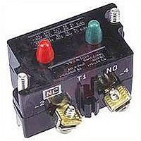
10250T3
Manufacturer Part Number
10250T3
Description
CONTACT BLOCK, 2NC, 6A, SCREW
Manufacturer
EATON CUTLER HAMMER
Datasheet
1.10250T101.pdf
(244 pages)
Specifications of 10250T3
No. Of Poles
2
Contact Current Max
6A
Contact Voltage Ac Max
600V
Contact Voltage Dc Max
250V
Switch Terminals
Screw
For Use With
10250T Series Pushbuttons And Indicating Lights
Lead Free Status / RoHS Status
Contains lead / RoHS non-compliant


March 2008
Push-Pull Operators
An illuminated Push-Pull pushbutton
unit, arranged for one-hole mounting,
can replace two pushbuttons and a
pilot light or the non-illuminated form
can replace two pushbuttons. These
units are available in three basic types:
■
Table 47-277. Push-Pull Operator Components
2-Position Operator without Lens
3-Position Operator without Lens
Note: Use NEMA 4X 10250T operators where exposed to ultraviolet light, see Pages 47-115 – 47-165.
Note: See Typical Applications on Page 47-129.
CA08102001E
Type of Operator
Maintained Push-Pull
Momentary Push-Pull
Maintained Push-Momentary Pull
Momentary Push-Pull
Special function contact blocks shown on
Maintained — (Two-Position).
Maintains in the pulled or pushed
position until manually actuated to
the opposite mode.
2-Position Maintained
Push-Pull without
Button on Lens
Catalog Number
E34GDB
Catalog
Number
E34GDB
E34GEB
E34GFB
E34GHB
Page 47-182
■
■
The Operators, Buttons, Contact
Blocks, etc., are offered as building
block components that can be inter-
mixed to satisfy many requirements.
This minimizes the need for a varied
and costly inventory.
For more information visit: www.eaton.com
Momentary — (Three-Position).
Spring returns to an intermediate
position when pulled or pushed and
released.
Momentary Pull, Maintained Push
— (Three-Position). Spring returns
to intermediate position when pulled.
Maintains in pushed position until
manually returned to intermediate
(ready to reset) position. Maintained
stop holds circuit open and will
prevent other series connected
operators from starting the system.
Pushbuttons & Indicating Lights
30.5 mm Corrosion Resistant Watertight/Oiltight
E34 Series, Push-Pull Components
CANNOT be used with 3-position push-pull operators E34GEB, E34GFB or E34GHB.
Price
U.S. $
Contact Block —
Max. of 2 Blocks,
4 Circuits
1NO
1NC
2NO
2NC
1NO
1NC
2NO
2NC
1NO
1NC
2NO
2NC
Operator Position and Circuit Arrangement
Out — Pull
Contact Block Mounting Location
A
O
O
O
O
O
O
X
X
X
X
X
X
or
or
or
Application Guide
To assist in the selection of contact
blocks, the sketch to the right shows
pictorially by symbols A and B locations
of contact circuits after assembly of
contact blocks and adapter to the oper-
ator. The chart below shows the effect
of the push and pull operations on
either NO or NC contacts. (X = contact
closed, O = contact open)
Figure 47-124. Contact Circuit Locations
Button or Lens . . . . . . . . . . . Page 47-176
Contact Blocks . . . . . . . . . . Page 47-182
Dimensions. . . . . . . . . . . . . . Page 47-191
Enclosures . . . . . . . . . . . . . . Pages 47-185 – 47-186
Legend Plates . . . . . . . . . . . Page 47-184
Discount Symbol . . . . . . . . . 1CD1C
B
O
X
O
X
O
X
O
X
O
X
O
X
Intermediate
No Intermediate
Position
A
O
O
O
O
O
O
O
O
or
or
Locating Nib
B
O
X
O
X
O
O
O
O
In — Push
A
X
O
X
O
X
O
X
O
X
O
X
O
A
B
or
or
or
X
O
X
O
O
O
O
O
X
O
X
O
B
47-175
47
Related parts for 10250T3
Image
Part Number
Description
Manufacturer
Datasheet
Request
R

Part Number:
Description:
10250 STD. DUTY RECTANGULAR PB
Manufacturer:
EATON CUTLER HAMMER
Part Number:
Description:
10250 STD. DUTY RECTANGULAR PB
Manufacturer:
EATON CUTLER HAMMER
Part Number:
Description:
Handle Tie Bar For (2) - 1 Pole Type BR Breakers
Manufacturer:
EATON CUTLER HAMMER
Part Number:
Description:
Type CL Breaker 25A/1Pole 120/240V 10K-Classified 1" Ckt Bkr
Manufacturer:
EATON CUTLER HAMMER