ADXRS401ABG-REEL Analog Devices Inc, ADXRS401ABG-REEL Datasheet - Page 10
ADXRS401ABG-REEL
Manufacturer Part Number
ADXRS401ABG-REEL
Description
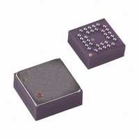
IC GYROSCOPE SGL COND 32CSPBGA
Manufacturer
Analog Devices Inc
Datasheet
1.ADXRS401ABG.pdf
(12 pages)
Specifications of ADXRS401ABG-REEL
Range °/s
±75°/s
Sensitivity
15mV/°/s
Typical Bandwidth
40Hz
Voltage - Supply
4.75 V ~ 5.25 V
Current - Supply
6mA
Output Type
Ratiometric
Operating Temperature
-40°C ~ 85°C
Package / Case
32-CSPBGA
For Use With
ADXRS401EB - EVAL BOARD FOR ADXRS401ABG
Lead Free Status / RoHS Status
Contains lead / RoHS non-compliant


ADXRS401
USE WITH A SUPPLY-RATIOMETRIC ADC
The ADXRS401’s RATEOUT signal is nonratiometric (that is,
neither the null voltage nor the rate sensitivity is proportional to
the supply). Rather, they are nominally constant for dc supply
changes within the 4.75 V to 5.25 V operating range. If the
ADXRS401 is used with a supply-ratiometric ADC, the
ADXRS401’s 2.5 V output can be converted and used to make
corrections in software for the supply variations.
NULL ADJUST
Null adjustment is possible by injecting a suitable current to
SUMJ (1C, 2C). Simply add a suitable resistor to either the
ground or the positive supply. The nominal 2.5 V null is for a
symmetrical swing range at RATEOUT (1B, 2A). In some
applications, a nonsymmetrical output swing may be suitable.
If a resistor is connected to the positive supply, supply
disturbances may reflect some null instability. Avoid digital
supply noise, particularly in this case (see the Supply and
Common Considerations section).
The resistor value to use is approximately:
V
null value. If the initial value is below the desired value, the
resistor should terminate on common or ground. If it is above
the desired value, the resistor should terminate on the 5 V
supply. Values typically are in the 1 MΩ to 5 MΩ range.
If an external resistor is used across RATEOUT and SUMJ, the
parallel equivalent value is substituted into the above equation.
Note that the resistor value is an estimate since it assumes
V
SELF-TEST FUNCTION
The ADXRS401 includes a self-test feature that stimulates each
of the sensing structures and associated electronics in the same
manner, as if subjected to angular rate. It is activated by
standard logic high levels applied to inputs ST1 (5F, 5G), ST2
(4F, 4G), or both. ST1 causes the voltage at RATEOUT to
change about −0.800 V, and ST2 causes an opposite +0.800 V.
Activating both ST1 and ST2 simultaneously is not damaging.
Because ST1 and ST2 are not necessarily closely matched,
actuating both simultaneously may result in an apparent null
bias shift.
NULL0
CC
= 5.0 V and V
R
NULL
is the unadjusted zero rate output, and V
=
(2.5
SUMJ
×
180,000)/(
= 2.5 V.
V
NULL0
–
V
NULL1
)
NULL1
is the target
Rev. 0 | Page 10 of 12
ACCELERATION SENSITIVITY
The sign convention used is that lateral acceleration is positive
in the direction from Pin Column A to Pin Column G of the
package. That is, a device has positive sensitivity if its voltage
output increases when the row of Pins 2A to 6A are tipped
under the row 2G to 6G in the Earth’s gravity.
There are two effects of concern: shifts in the static null and
induced null noise. Scale factor is not significantly affected until
acceleration reaches several hundred meters per second
squared.
Vibration rectification for frequencies up to 20 kHz is of the
order of 0.00002(°/s)/(m/s
0.0003(°/s)/(m/s
the lid. It is not significantly dependent on frequency, and has
been verified up to 300 m/s
Linear vibration spectral density near the 14 kHz sensor
resonance translates into output noise. In order to have a
significant effect, the vibration must be within the angular rate
bandwidth (typically ±40 Hz of the resonance), so it takes
considerable high frequency vibration to have any effect.
Away from the 14 kHz resonance, the effect is not discernible,
except for vibration frequencies within the angular rate pass
band. The in-band effect can be seen in Figure 17. This is the
result of the static g-sensitivity. The specimen used for Figure 17
had a g-sensitivity of 0.15 °/s/g and its total in-band noise
degraded from 3 mV rms to 5 mV rms for the specified
vibration. The effect of broadband vibration up is shown in
Figure 18 and Figure 19.
The output noise of the part falls away in accordance with the
output low-pass filter and does not contain any spikes greater
than 1% of the low frequency noise. A typical noise spectrum is
shown in Figure 16.
–100
–110
–120
–130
–60
–70
–80
–90
Figure 16. Noise Spectral Density at RATEOUT – BW = 4Hz
0
2
)
2
10
for acceleration applied along a diagonal of
2
)
2
FREQUENCY (Hz)
2
100
rms.
in the primary axis and
1k
10k
100k
Related parts for ADXRS401ABG-REEL
Image
Part Number
Description
Manufacturer
Datasheet
Request
R

Part Number:
Description:
±1.7g Dual-Axis IMEMS Accelerometer Evaluation Board
Manufacturer:
Analog Devices Inc
Datasheet:

Part Number:
Description:
Inertial Sensor Evaluation System
Manufacturer:
Analog Devices Inc
Datasheet:
Part Number:
Description:
Manufacturer:
Analog Devices Inc
Datasheet:
Part Number:
Description:
Manufacturer:
Analog Devices Inc
Datasheet:
Part Number:
Description:
Manufacturer:
Analog Devices Inc
Datasheet:
Part Number:
Description:
Manufacturer:
Analog Devices Inc
Datasheet:
Part Number:
Description:
Manufacturer:
Analog Devices Inc
Datasheet:
Part Number:
Description:
Manufacturer:
Analog Devices Inc
Datasheet:
Part Number:
Description:
Manufacturer:
Analog Devices Inc
Datasheet:
Part Number:
Description:
Manufacturer:
Analog Devices Inc
Datasheet:
Part Number:
Description:
Manufacturer:
Analog Devices Inc
Datasheet:
Part Number:
Description:
Manufacturer:
Analog Devices Inc
Datasheet:
Part Number:
Description:
Manufacturer:
Analog Devices Inc
Datasheet: