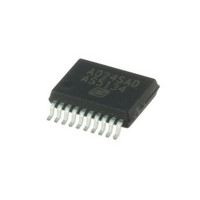
AS5134-ZSST austriamicrosystems, AS5134-ZSST Datasheet - Page 15

AS5134-ZSST
Manufacturer Part Number
AS5134-ZSST
Description
IC ENCODER PROG 20-SSOP
Manufacturer
austriamicrosystems
Type
Linear, Rotary Encoder - Programmabler
Datasheet
1.AS5134_PB.pdf
(40 pages)
Specifications of AS5134-ZSST
Sensing Range
20mT ~ 80mT
Voltage - Supply
4.5 V ~ 5.5 V
Current - Supply
15mA
Output Type
Digital, PWM
Features
Programmable
Operating Temperature
-40°C ~ 140°C
Package / Case
20-SSOP
Lead Free Status / RoHS Status
Lead free / RoHS Compliant
Current - Output (max)
-
Other names
AS5134-ZSSTTR
Available stocks
Company
Part Number
Manufacturer
Quantity
Price
Company:
Part Number:
AS5134-ZSST
Manufacturer:
ICT
Quantity:
1 200
AS5134
Data Sheet - D e t a i l e d D e s c r i p t i o n
7.7 Analog Output
This configuration is similar to the PWM connection (only three lines including supply are required). With the addition of a lowpass filter at the
PWM output, this configuration produces an analog voltage that is proportional to the angle. This filter can be either passive (as shown in
Figure
invalid, the PWM output will remain at low state and thus the analog output will be 0V. Pins that are not shown may be left open.
Figure 9. Data Transmission with Pulse Width Modulated (PWM) Output
7.8 Quadrature A/B/Index Output
The phase shift between channel A and B indicates the direction of the magnet movement. Channel A leads channel B at a clockwise rotation of
the magnet (top view) by 90 electrical degrees. Channel B leads channel A at a counter-clockwise rotation.
Figure 10. Incremental Output Modes
Table 7. Programming Options for the Quadrature Signals A/B/Index
www.austriamicrosystems.com/AS5134
VSS
100nF
VDD
+5V
9) or active. The lower the bandwidth of the filter, the less ripple of the analog output can be achieved. If the AS5134 angular data is
0
0
1
1
Quad A/B/Index-Mode
Abi (13:12)
CS
AS5134
Index
B
A
C2
VSS
PWM
VDD
0
1
0
1
>=4k7
>=1µF
>=4k7
>=1µF
Revision 1.13
A → pin A, B → pin B, I(index) → pin I default value)
Zero Position
Mechanical
pulse → pin A, direction → pin B, I(index) → pin I
step → pin A, direction → pin B, I(index) → pin I
Analog
out
Index=0
3 LSB
1 LSB
Function: output multiplexer for pin A,B,I
max.
off: LO → pin A, LO → pin B, LO → pin I
5V
0V
Rotation Direction
0º
Change
Hyst=
2LSB
180º
Zero Position
Mechanical
360º
Analog out
PWM out
Angle
15 - 40


