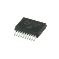
AS5134-ZSST austriamicrosystems, AS5134-ZSST Datasheet - Page 23

AS5134-ZSST
Manufacturer Part Number
AS5134-ZSST
Description
IC ENCODER PROG 20-SSOP
Manufacturer
austriamicrosystems
Type
Linear, Rotary Encoder - Programmabler
Datasheet
1.AS5134_PB.pdf
(40 pages)
Specifications of AS5134-ZSST
Sensing Range
20mT ~ 80mT
Voltage - Supply
4.5 V ~ 5.5 V
Current - Supply
15mA
Output Type
Digital, PWM
Features
Programmable
Operating Temperature
-40°C ~ 140°C
Package / Case
20-SSOP
Lead Free Status / RoHS Status
Lead free / RoHS Compliant
Current - Output (max)
-
Other names
AS5134-ZSSTTR
Available stocks
Company
Part Number
Manufacturer
Quantity
Price
Company:
Part Number:
AS5134-ZSST
Manufacturer:
ICT
Quantity:
1 200
AS5134
Data Sheet - A p p l i c a t i o n I n f o r m a t i o n
Figure 15. OTP Programming Connection
Note: The maximum capacitive load at PROG in normal operation should be less than 10pF. However, during programming the capacitors
8.1.2 Programming Verification
After programming, the programmed OTP bits may be verified in two ways:
By Digital Verification: This is simply done by sending a READ OTP command (#15). The structure of this register is the same as for the OTP
PROG or OTP WRITE commands.
By Analog Verification: By switching into Extended Mode and sending an ANALOG OTP READ command (#9), pin PROG becomes an output,
sending an analog voltage with each clock representing a sequence of the bits in the OTP register (starting with D61). A voltage of <500mV
indicates a correctly programmed bit (“1”) while a voltage level between 2.2V and 3.5V indicates a correctly unprogrammed bit (“0”). Any voltage
level in between indicates incorrect programming.
www.austriamicrosystems.com/AS5134
Remove for normal operation
V
C1+C2 are needed to buffer the programming voltage during current spikes, but they must be removed for normal operation. To over-
come this contradiction, the recommendation is to add a diode (4148 or similar) between PROG and V
cial case setup), if the capacitors can not be removed at final assembly.
Due to D1, the capacitors C1+C2 are loaded with V
During programming the OTP, the diode ensures that no current is flowing from PROG (8-8.5V) to VDD (5V).
In the standard case (see
ister or with the aid of the otp_ok bit. The special case setup provides only the otp_ok bit for verifying the correct reading of the OTP.
Analog readback is not usable in the special case mode, as the diode pulls the PROG pin to V
The otp_ok bit can be accessed with command #4
As long as the PROG pin is accessible it is recommended to use standard setup. In case the PROG pin is not accessible at final
assembly, the special setup is recommended.
zapp
Standard Case
100nF
C1
10µF
C2
parasitic cable
inductance
maximum
L<50nH
V
prog
Figure
GND
PROG
15), the verification of a correct OTP readout can be done either by analog readback of the OTP reg-
PROM Cell
V
DD
V
SUPPLY
(see Table
DD
-0.7V at startup, hence not influencing the readout of the internal OTP registers.
Revision 1.13
9).
V
zapp
Special Case
100nF
C1
10µF
C2
L<50nH
DD
V
.
prog
DD
GND
PROG
as shown in
PROM Cell
V
DD
V
SUPPLY
Figure 15
23 - 40
(spe-


