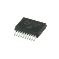
AS5134-ZSST austriamicrosystems, AS5134-ZSST Datasheet - Page 6

AS5134-ZSST
Manufacturer Part Number
AS5134-ZSST
Description
IC ENCODER PROG 20-SSOP
Manufacturer
austriamicrosystems
Type
Linear, Rotary Encoder - Programmabler
Datasheet
1.AS5134_PB.pdf
(40 pages)
Specifications of AS5134-ZSST
Sensing Range
20mT ~ 80mT
Voltage - Supply
4.5 V ~ 5.5 V
Current - Supply
15mA
Output Type
Digital, PWM
Features
Programmable
Operating Temperature
-40°C ~ 140°C
Package / Case
20-SSOP
Lead Free Status / RoHS Status
Lead free / RoHS Compliant
Current - Output (max)
-
Other names
AS5134-ZSSTTR
Available stocks
Company
Part Number
Manufacturer
Quantity
Price
Company:
Part Number:
AS5134-ZSST
Manufacturer:
ICT
Quantity:
1 200
AS5134
Data Sheet - E l e c t r i c a l C h a r a c t e r i s t i c s
6 Electrical Characteristics
T
Table 3. Electrical Characteristics
www.austriamicrosystems.com/AS5134
System Parameters
Magnet Specifications
PWM Output
Programming Parameters
AMB
Symbol
PW
T
PW
V
INL
N
I
B
t
f
t
B
PROG
V
PwrUp
I
delay
PWM
PWM
PROG
MD
MT
TN
= -40 to 140ºC, VDD5V = 4.5-5.5V, all voltages referenced to V
I
PWM
DD
T
imax
imin
V
DD
N
t
off
s
MAX
MIN
J
cm
i
Horizontal magnet displacement radius
Magnetic Input Range Max.
Vertical distance of magnet
Magnetic Input Range Min.
Positive Supply Voltage
Magnet rotation speed
Junction Temperature
Programming Voltage
Programming Current
Power down current
Operating Current
Propagation delay
Magnet thickness
PWM pulse width
PWM pulse width
Magnet diameter
Hall Array radius
PWM resolution
PWM frequency
Transition noise
Power Up Time
Tracking rate
PWM period
Parameter
Resolution
Accuracy
No load on outputs. Supply current can
be reduced by using stronger magnets.
Within horizontal displacement radius
Max X-Y Offset between chip center
Max X-Y Offset between defined IC
Package center and magnet axis
Startup from Low Power mode
Internal signal processing time
Step rate of tracking ADC;
Diametrically magnetized
Static voltage at pin Prog
to maintain locked state
Angle = 360º (FF
Revision 1.13
Low Power Mode
Startup from zero
Centered Magnet
=1 / PWM period
and magnet axis
Angle = 0º (00
SS
at chip surface
Conditions
1 Step = 1º
Peak-Peak
1 step = 1º
, unless otherwise noted.
(4.4)
H
)
H
)
Min
4.5
3.0
0.5
8.0
-2
-3
1.33
Typ
734
750
8.5
2.5
8.5
70
22
20
80
16
6
2
1
4
1
1
82.000
≤4100
≤500
Max
+5.5
1.41
0.25
0.48
120
170
100
5.2
1.8
8.5
15
2
3
µs/step
µs/step
Units
Deg
Deg
Deg
Deg
rpm
kHz
mm
mm
mm
mm
mm
mA
mT
mA
µA
ºC
Bit
µs
µs
Bit
µs
µs
µs
V
V
6 - 40


