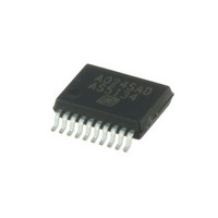
AS5134-ZSST austriamicrosystems, AS5134-ZSST Datasheet - Page 27

AS5134-ZSST
Manufacturer Part Number
AS5134-ZSST
Description
IC ENCODER PROG 20-SSOP
Manufacturer
austriamicrosystems
Type
Linear, Rotary Encoder - Programmabler
Datasheet
1.AS5134_PB.pdf
(40 pages)
Specifications of AS5134-ZSST
Sensing Range
20mT ~ 80mT
Voltage - Supply
4.5 V ~ 5.5 V
Current - Supply
15mA
Output Type
Digital, PWM
Features
Programmable
Operating Temperature
-40°C ~ 140°C
Package / Case
20-SSOP
Lead Free Status / RoHS Status
Lead free / RoHS Compliant
Current - Output (max)
-
Other names
AS5134-ZSSTTR
Available stocks
Company
Part Number
Manufacturer
Quantity
Price
Company:
Part Number:
AS5134-ZSST
Manufacturer:
ICT
Quantity:
1 200
AS5134
Data Sheet - A p p l i c a t i o n I n f o r m a t i o n
If only the SIN-/COS-outputs are used, the propagation delay is the analog signal path delay only (typ. 15.6µs).
8.4.5.1
The angle error over speed caused by the propagation delay is calculated as:
In addition, the anti-aliasing filter causes an angle error calculated as:
Table 12. Examples of the Overall Position Error caused by Speed (includes both propagation delay and filter delay)
8.4.6 Low Power Mode
The target of this mode is to reduce the long time power consumption of the device for battery powered applications, without losing the actual
angle information.
In Low Power Mode, the AS5134 is inactive. The last state (for e.g. the angle, AGC value, etc.) is frozen and the chip starts from this frozen state
when it resumes active operation. This method provides much faster start-up than a “cold start” from zero. If the AS5134 is cycled between
active and reduced current mode, a substantial reduction of the average supply current can be achieved. The minimum dwelling time is <0.5 ms.
The actual active time depends on how much the magnet has moved while the AS5134 was in reduced power mode. The angle data is valid,
when the status bit LOCK has been set. Once a valid angle has been measured, the AS5134 can be put back to reduced power mode. The
average power consumption can be calculated as:
Where:
I
I
I
t
t
To access the Low Power Mode, the bit ‘LP’ <15> of the digital interface has to be set to “1”.
Figure 18. Low Power Mode Connection
www.austriamicrosystems.com/AS5134
avg
active
power_down
on
off
= Time period during which the chip is in reduced power mode
= Time period during which the chip is operated in active mode
= Average current consumption
= Current consumption in active mode
Position Error Over Speed:
= I
off
: Current consumption in reduced power mode (max. 120µA)
Speed (rpm)
10000
C1
1000
100
I
avg
=
I
-------------------------------------------------------------------- -
active
100nF
∗ t
on
AS5134
Δθ
t
on
+
Δ
pd
I
S
+
θ
VDD
powerdown
VSS
= rpm * 6 * 17 * E
lpf
t
off
= ArcTan [rpm / (60 * f0)]
N
C2
∗ t
Revision 1.13
off
I
I
-6
on
off
CS
DIO
R1
DCLK
in degrees
t
on
sampling interval = t
t
off
Total Position Error (Δθ
on/off
Controller
VDD
VSS
Micro
on
0,0175º
0,175º
1,75º
+ t
off
VDD
+5V
VSS
pd +
Δ
θ
lpf
)
(EQ 3)
(EQ 4)
(EQ 5)
27 - 40


