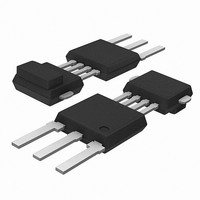
KMI18/2,115 NXP Semiconductors, KMI18/2,115 Datasheet - Page 3

KMI18/2,115
Manufacturer Part Number
KMI18/2,115
Description
SPEED SENSOR ROTATIONAL SOT477A
Manufacturer
NXP Semiconductors
Type
Special Purposer
Datasheet
1.KMI182115.pdf
(12 pages)
Specifications of KMI18/2,115
Sensing Range
±400A/m
Voltage - Supply
4.5 V ~ 16.5 V
Current - Supply
10mA
Current - Output (max)
20mA
Output Type
Digital, Open Collector
Features
Gear Tooth Type
Operating Temperature
-40°C ~ 150°C
Package / Case
SOT-477A
Maximum Operating Temperature
+ 150 C
Mounting Style
Through Hole
Lead Free Status / RoHS Status
Lead free / RoHS Compliant
Other names
934056231115
KMI18/2 T/R
KMI18/2 T/R
KMI18/2 T/R
KMI18/2 T/R
Available stocks
Company
Part Number
Manufacturer
Quantity
Price
Part Number:
KMI18/2,115
Manufacturer:
NXP/恩智浦
Quantity:
20 000
Philips Semiconductors
LIMITING VALUES
In accordance with Absolute Maximum Rating System (IEC 60134); T
Notes
1. Low: transistor open (V
2. High: transistor closed (V
CHARACTERISTICS
T
otherwise specified.
2000 Sep 05
V
V
I
I
P
T
T
T
Sensor characteristics
H
H
H
H
H
f
Supply conditions
I
V
Signal output characteristics
I
SYMBOL
SYMBOL
OUT(max)
OUT(high)
amb
rm
CC
OUT
amb
stg
sld
CC
OUT
tot
CC
yLH
yHL
y0
yh
x
Integrated rotational speed sensor
= 26
10 C; V
DC supply voltage
output voltage
maximum output current
output leakage current
total power dissipation
ambient operating temperature
storage temperature
soldering temperature
magnetic trigger field strength
(threshold) for LH-output edge
magnetic trigger field strength
(threshold) for HL-output edge
magnetic offset
magnetic trigger hysteresis
auxiliary magnetic field strength
frequency of magnetic reference
marks
DC supply current
DC supply voltage
transfer behaviour
power-on state
output current
CC
PARAMETER
= 5 V; f
PARAMETER
CE
CE
< 1 V).
rm
> 4 V).
= 0 to 25000 Hz; magnetic reading point according to ‘Package outline’; unless
not protected against incorrect polarity
not protected against incorrect polarity
low state; note 1
high state; note 2; see Fig.5
high state; note 2; see Fig.6
V
V
t
CC
CC
10 s
= 16.5 V; I
= 5 V
T
T
T
T
T
V
T
V
T
change of magnetic
reference field H
low state; note 1
amb
amb
amb
amb
amb
amb
amb
CC
CC
= 5 V
= 5 V
= 25 C
= 40 to +150 C
= 25 C
= 40 to +150 C
= 26
= 40 to +150 C;
= 40 to +150 C
CONDITIONS
3
CONDITIONS
OUT
10 C;
= 20 mA
y
amb
= 40 to +150 C; see Fig.4.
100
100
5
0
6.5
6
4.5
NS
SN
undefined
0.1
200
400
600
150
MIN.
HL
LH
0.5
0.5
40
40
MIN.
250
+250
500
8
7.5
7
5
250
250
TYP.
Preliminary specification
+16.5
+24
20
100
100
300
+150
+150
260
MAX.
400
+600
+200
+150
700
10
25000
8.5
10
16.5
20
MAX.
100
KMI18/2
V
V
mA
mW
C
C
C
A/m
A/m
A/m
A/m
A/m
A/m
kA/m
Hz
mA
mA
V
mA
A
A
UNIT
UNIT


