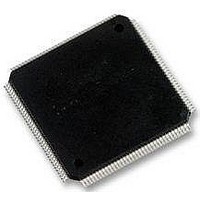
STM32F103ZGH6 STMicroelectronics, STM32F103ZGH6 Datasheet - Page 101

STM32F103ZGH6
Manufacturer Part Number
STM32F103ZGH6
Description
MCU 32BIT 1MB FLASH 144LQFP
Manufacturer
STMicroelectronics
Series
STM32r
Datasheet
1.STM32F103VGT6.pdf
(120 pages)
Specifications of STM32F103ZGH6
Core Processor
ARM® Cortex-M3™
Core Size
32-Bit
Speed
72MHz
Connectivity
CAN, I²C, IrDA, LIN, MMC, SPI, UART/USART, USB
Peripherals
DMA, I²S, LCD, POR, PWM, WDT
Number Of I /o
112
Program Memory Size
1MB (1M x 8)
Program Memory Type
FLASH
Ram Size
96K x 8
Voltage - Supply (vcc/vdd)
2 V ~ 3.6 V
Data Converters
A/D 21x12b; D/A 2x12b
Oscillator Type
Internal
Operating Temperature
-40°C ~ 85°C
Package / Case
*
Processor Series
STM32F101xG
Core
ARM Cortex M3
Data Bus Width
32 bit
Data Ram Size
80 KB
Interface Type
I2C, SPI, UART
Maximum Clock Frequency
36 MHz
Number Of Programmable I/os
112
Number Of Timers
15
Operating Supply Voltage
2 V to 3.6 V
Maximum Operating Temperature
+ 85 C
Mounting Style
SMD/SMT
Operating Temperature Range
- 40 C to + 105 C
Processor To Be Evaluated
STM32F103ZG
Supply Current (max)
28 mA
Lead Free Status / RoHS Status
Lead free / RoHS Compliant
Eeprom Size
-
Lead Free Status / Rohs Status
Details
Other names
497-11115
Available stocks
Company
Part Number
Manufacturer
Quantity
Price
Company:
Part Number:
STM32F103ZGH6
Manufacturer:
STMicroelectronics
Quantity:
135
Company:
Part Number:
STM32F103ZGH6
Manufacturer:
STMicroelectronics
Quantity:
10 000
Part Number:
STM32F103ZGH6
Manufacturer:
ST
Quantity:
20 000
STM32F103xF, STM32F103xG
5.3.18
Table 57.
1. All the voltages are measured from the local ground potential.
2. To be compliant with the USB 2.0 full-speed electrical specification, the USBDP (D+) pin should be pulled
3. The STM32F103xx USB functionality is ensured down to 2.7 V but not the full USB electrical
4. Guaranteed by characterization, not tested in production.
5. R
Figure 54. USB timings: definition of data signal rise and fall time
Table 58.
1. Guaranteed by design, not tested in production.
2. Measured from 10% to 90% of the data signal. For more detailed informations, please refer to USB
CAN (controller area network) interface
Refer to
function characteristics (CAN_TX and CAN_RX).
Input levels
Output levels
Symbol
Symbol
V
V
V
V
V
up with a 1.5 k resistor to a 3.0-to-3.6 V voltage range.
characteristics which are degraded in the 2.7-to-3.0 V V
V
Specification - Chapter 7 (version 2.0).
V
CM
SE
DI
t
DD
OH
L
CRS
OL
rfm
t
t
(4)
r
f
(4)
is the load connected on the USB drivers
(4)
Section 5.3.14: I/O port characteristics
USB operating voltage
Differential input sensitivity
Differential common mode range Includes V
Single ended receiver threshold
Static output level low
Static output level high
data lines
Differen tial
Rise time
Fall Time
Rise/ fall time matching
Output signal crossover voltage
USB DC electrical characteristics
USB: full-speed electrical characteristics
V CRS
V S S
(2)
(2)
Parameter
Parameter
t f
Doc ID 16554 Rev 2
(2)
Crossover
points
Driver characteristics
t r
I(USBDP, USBDM)
R
R
L
L
of 1.5 k
of 15 k
Conditions
C
C
for more details on the input/output alternate
L
L
DD
Conditions
= 50 pF
= 50 pF
t
r
voltage range.
/t
DI
f
to V
range
to 3.6 V
(1)
SS
(5)
(5)
Min
1.3
90
4
4
Electrical characteristics
Min.
3.0
0.2
0.8
1.3
2.8
(3)
(1)
Max
110
2.0
20
20
Max.
ai14137
2.0
3.6
2.5
0.3
3.6
(1)
Unit
101/120
ns
ns
%
V
Unit
V
V
V


