T1620000 Red Lion Controls, T1620000 Datasheet - Page 8
T1620000
Manufacturer Part Number
T1620000
Description
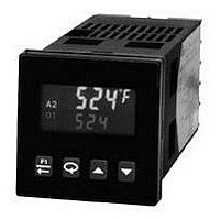
Process/Temperature Controller
Manufacturer
Red Lion Controls
Type
Temperaturer
Specifications of T1620000
Operating Temperature Max
50°C
Operating Temperature Min
0°C
Temperature Accuracy ±
0.3%
Output Voltage Max
7V
Output Voltage Min
4V
Controller Input
Thermocouple Or RTD
Brand/series
T16 Series
Dimensions
49.5mmW×49.5mmH×115.3mmD
Enclosure Rating
IP65
Input Type
RTD/Thermocouple
Ip Rating
IP65
Memory
EEPROM
Mounting Type
Panel
Output Type
Digital/SSR
Power, Rating
8 VA
Primary Type
Controller
Special Features
EEPROM
Standards
cURus, CE
Termination
Screw
Voltage, Supply
85 to 250 VAC
Thermocouple Type
J, K, T, E, R, S, B, N, C And Linear MV
Rohs Compliant
Yes
Lead Free Status / RoHS Status
Lead free / RoHS Compliant


The values shown for the displays are the factory settings.
display. There is no annunciator nor parameter indication for Setpoint in the
Display Loop. The parameter name alternates with the setpoint value in the
Hidden Loop. The Setpoint value can be changed, activated and stored by
pressing the arrow keys. This is the only parameter that can be configured as
read only in the Display Loop, but read/write in the Hidden Loop. It is possible
to store a second Setpoint value that can be selected in the Hidden Loop, by the
F1 key or the user input. Both Setpoint values are limited by the Setpoint Low
and High Limits in Input Module
name alternates with the % Output Power value in the Hidden Loop. While the
controller is in Automatic Mode, this value is read only. When the controller is
placed in Manual Mode, the value can be changed, activated and stored by
pressing the arrow keys. For more details on % Output Power, see Control
Mode Explanations.
Mode, this parameter will appear after % Output Power. It is also shown with
the %PW annunciator illuminated. The power offset is used to shift the
proportional band to compensate for errors in the steady state. If Integral Action
is later invoked, the controller will re-calculate the internal integral value to
provide “bumpless” transfer and Output Power Offset will not be necessary.
disturbance while minimizing overshoot. A proportional band of 0.0% forces
the controller into On/Off Control with its characteristic cycling at Setpoint. For
more information, see Control Mode and PID Tuning Explanations.
Typically, the controller is operating with the Setpoint value in the bottom
The % Output Power is shown with the %PW annunciator. The parameter
OPOF
When the Integral Time is set to zero and the controller is in the Automatic
ProP
The proportional band should be set to obtain the best response to a process
SP
SP
OP
0. 0
2. 0
0. 0
0. 0
4. 0
0
T16
P16
T16
P16
OUTPUT POWER OFFSET
SETPOINT VALUE (SP1) *
SETPOINT VALUE (SP2) *
PROPORTIONAL BAND
(% of full input range)
% OUTPUT POWER *
-999
-999
-100
-100
0. 0
to
to
to
to
to
.
999. 9
9999
9999
100. 0
100. 0
8
* Alternating indication only used in the Hidden Loop.
eliminate error in the steady state. The higher the integral time, the slower the
response. The optimal integral time is best determined during PID Tuning. If
time is set to zero, the previous Integral output power value is maintained.
Offset Power can be used to provide Manual Reset.
time, coupled with noisy signal processes, may cause the output to fluctuate too
greatly, yielding poor control. Setting the time to zero disables derivative action.
is either absolute (absolute alarm types) or relative to the Setpoint value
(deviation and band alarm types.) When Alarm 1 is programmed for HEAt or
NonE, this parameter is not available. For more details on alarms, see Alarm
Module
is either absolute (absolute alarm types) or relative to the Setpoint value
(deviation and band alarm types.) When Alarm 2 is programmed for CooL or
NonE, this parameter is not available. For more details on alarms, see the Alarm
Module 4-AL.
Intt
Integral action shifts the center point position of the proportional band to
dErt
Derivative time helps to stabilize the response, but too high of a derivative
AL-1
On models with alarms, the value for Alarm 1 can be entered here. The value
AL-2
On models with alarms, the value for Alarm 2 can be entered here. The value
120
30
0. 0
0. 0
.
0
0
T16
P16
T16
P16
0
0
to
to
DERIVATIVE TIME
-999
ALARM 1 VALUE
ALARM 2 VALUE
INTEGRAL TIME
9999
9999
-999
to
to
seconds per repeat
seconds
9999
9999
Related parts for T1620000
Image
Part Number
Description
Manufacturer
Datasheet
Request
R

Part Number:
Description:
Counter
Manufacturer:
Red Lion Controls
Datasheet:
Part Number:
Description:
Miniature Length Sensor
Manufacturer:
Red Lion Controls
Datasheet:
Part Number:
Description:
Model Lsc - Single Channel Output Length Sensor
Manufacturer:
Red Lion Controls
Datasheet: