PD3-013-42 TRINAMIC, PD3-013-42 Datasheet - Page 17
PD3-013-42
Manufacturer Part Number
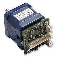
PD3-013-42
Description
STEPPER MOTOR, PANDRIV, 42MM, 0.50NM
Manufacturer
TRINAMIC
Datasheet
1.PD3-013-42.pdf
(27 pages)
Specifications of PD3-013-42
Coil Type
Bipolar
Torque Max
0.49N-m
Current Rating
1A
External Depth
42mm
External Length / Height
49.5mm
External Width
42mm
Holding Torque
0.49N-m
Overall Length
69mm
Steps Per
RoHS Compliant
Svhc
No SVHC (15-Dec-2010)
Rohs Compliant
Yes


6.2.1.1 Example for test move:
6.2.1.2 Motor Current (C)
The motor current can be set by the user. To do this use the RS485 command “AC” in addition with a
percent value. To calculate the actual setting, please use the 100% values as shown in the table.
Internally the current is regulated by two independent parameters for the best module/motor
performance possible.
For chopper mode 2, the maximum setting is about 75% to 90% - at higher settings, motor microstep
behavior may become harsh. The actual maximum depends upon the actual motor. This is to avoid
the motor coil current raising above the 100% setting at any time.
Not all currents can be continuously driven at all supply voltages / cooling circumstances.
Please refer to motor current limitations.
*) Not possible for chopper mode 2.
6.2.1.3 Failure Readout (E)
The TMCM-013 provides a full driver failure analyses in SPI mode (8 Bit). The returned bit
assignments are as follows:
Bit
In the other two modes the failure analysis consists of only one bit:
Copyright © 2005, TRINAMIC Motion Control GmbH & Co. KG
7
6
5
4
3
2
1
0
•
•
•
Name
OT
OTPW
UV
OCHS
OLB
OLA
OCB
OCA
AA 500, AV 50000, AV –50000 ⇒ try other AA 0…8000, AV 0…400000
AA 500, AV 50000, AC 200 ⇒ test torque manually ⇒ AC 20 ⇒ test torque
AV 0, AR, AP 0, AR, AA 500, AV 50000, AR
1: short circuit or overtemperature
0: no failure
Different accelerations and velocities
Max. current – test of torque
Read and set position
Function
overtemperature
temperature prewarning
driver undervoltage
overcurrent high side
open load bridge B
open load bridge A
overcurrent bridge B low side
overcurrent bridge A low side
100
AC
80
66
50
33
20
0
Table 6.3: Failure readout in SPI mode
Table 6.2: Motor Current Examples
I
1.50A
1.20A
1.00A
0.75A
0.50A
0.30A
COIL,PP
0A
Remark
“1” = driver chip off due to overtemperature
“1” = driver chip prewarning temperature exceeded
“1” = undervoltage on VS
3 PWM cycles with overcurrent within 63 PWM cycles
Open load detection can occur at fast motion also.
Open load detection can occur at fast motion also.
Short circuit detected. Please check motor wiring.
Short circuit detected. Please check motor wiring.
I
COIL,RMS
1.06A
0.85A
0.71A
0.53A
0.35A
0.21A
0.00A
% to max.
100% *)
75%
66%
50%
33%
25%
I
0%
COIL
Related parts for PD3-013-42
Image
Part Number
Description
Manufacturer
Datasheet
Request
R

Part Number:
Description:
STEPPER MOTOR, PANDRIV, 57MM, 1.63NM
Manufacturer:
TRINAMIC
Datasheet:

Part Number:
Description:
STEPPER MOTOR, PANDRIV, 42MM, 0.50NM
Manufacturer:
TRINAMIC
Datasheet:
Part Number:
Description:
STEPPER MOTOR, PANDRIV, 42MM, 0.50NM
Manufacturer:
TRINAMIC
Datasheet:
Part Number:
Description:
STEPPER MOTOR, PANDRIV, 42MM, 0.50NM
Manufacturer:
TRINAMIC
Datasheet:

Part Number:
Description:
2.54mm Pitch Power Board To Boardconnector
Manufacturer:
DDK Ltd.
Datasheet:
Part Number:
Description:
28mm Nema11 Stepper Motor With Controller Driver Serial Interface
Manufacturer:
ETC-unknow
Datasheet:
Part Number:
Description:
3-way Wilkinson Power Divider
Manufacturer:
Marki Microwave
Datasheet:
Part Number:
Description:
3-way Wilkinson Power Divider
Manufacturer:
Marki Microwave
Datasheet:
Part Number:
Description:
57mm / NEMA23 Stepper Motor with Controller / Driver and Serial Interface
Manufacturer:
TRINAMIC [TRINAMIC Motion Control GmbH & Co. KG.]
Datasheet:
Part Number:
Description:
42mm / NEMA17 Stepper Motor with Controller / Driver and Serial Interface
Manufacturer:
TRINAMIC [TRINAMIC Motion Control GmbH & Co. KG.]
Datasheet:
Part Number:
Description:
57mm/NEMA23 or 60mm/NEMA24 Stepper Motor with Controller/Driver with Encoder and Serial Interface
Manufacturer:
TRINAMIC [TRINAMIC Motion Control GmbH & Co. KG.]
Datasheet:
Part Number:
Description:
60mm/NEMA24 Stepper Motor with Controller/Driver, with Encoder and Serial Interface
Manufacturer:
TRINAMIC [TRINAMIC Motion Control GmbH & Co. KG.]
Datasheet:
Part Number:
Description:
42mm/NEMA17 Stepper Motor with Controller/Driver, Encoderand Serial Interface
Manufacturer:
TRINAMIC [TRINAMIC Motion Control GmbH & Co. KG.]
Datasheet:
Part Number:
Description:
42mm/NEMA17 High Performance BLDC Motor with Controller/Driver and Serial Interface
Manufacturer:
TRINAMIC [TRINAMIC Motion Control GmbH & Co. KG.]
Datasheet:
Part Number:
Description:
57mm diameter BLDC Encoder Motor with Controller/Driver and Serial Interface
Manufacturer:
TRINAMIC [TRINAMIC Motion Control GmbH & Co. KG.]
Datasheet: