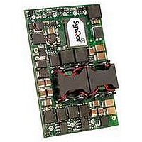
IQ65033QMA10END-G SYNQOR, IQ65033QMA10END-G Datasheet - Page 13

IQ65033QMA10END-G
Manufacturer Part Number
IQ65033QMA10END-G
Description
InQor DC/DC Converters
Manufacturer
SYNQOR
Datasheet
1.IQ65033QMA10END-G.pdf
(15 pages)
Specifications of IQ65033QMA10END-G
Dc / Dc Converter O/p Type
Fixed
No. Of Outputs
2
Input Voltage
36V To 75V
Output Voltage
5V
Output Current
10A
Output Voltage 2
3.3V
Approval Bodies
UL, CUL, TUV, IEC
Supply Voltage
48V
Lead Free Status / RoHS Status
Lead free / RoHS Compliant
Product # IQ65033QMA10
Table 1: Internal register memory map.
FULL FEATURE APPLICATION NOTES
I
version of the module, the iQor I
analog parameters and 6 status bits. The actual analog parameter
values are calculated by multiplying by the specified scaling
factors (see Table 1). The status bits are interpreted in Table 2.
The initial value of all registers is zero. Data in the registers begins
updating 300 ms after management power startup, and continues
updating at approximately 100 ms intervals during steady-state
operation. All registers are updated simulatneously.
Table 2: The status byte represents 6 different digital signals and
their digital state. Note: 1) Bit0 ⇒ LSb, Bit7 ⇒ MSb.
Data_Pointer
Bit
Technical Specification
2
1Eh
1Fh
21h
22h
23h
28h
C Data Reporting Interface: Available on the full feature
0
1
2
3
4
5
6
7
Value
ENABLE_A
ENABLE_B
ALARM
N/A
HOLDUP
HOTSWAP
VOUT_
LOW
N/A
Name
Parameter
Enable A Signal
State
Enable B Signal
State
Alarm Signal
State
Reserved
Holdup Switch
State
Hotswap Switch
State
-48V Output
Under-Voltage
Alarm
Reserved
Description Value
Status Bits
HU_CAP
-48V_Current
-48V_A
-48V_B
Temperature
Phone 1-888-567-9596
Digital Signals
(see Table 2)
Voltage between HU_
CAP and -48V_OUT
-48V Output Current
Voltage between
VRTN_A and -48V_A
Voltage between
VRTN_B and -48V_B
Average Unit
Temperature
Description
2
0
1
0
1
0
1
0
1
0
1
0
1
C Serial Interface monitors 5
EN_A is Disabled
EN_A is Enabled
EN_B is Disabled
EN_B is Enabled
Primary side Alarm is not SET
Primary side Alarm is SET
Holdup Cap is not connected
to -48V Out
Holdup Cap is connected
to -48V Out
Hotswap switch is OFF
Hotswap switch is ON
Output voltage is below
threshold
Output voltage is above
threshold
Translation
N/A
0.398 V/bit
0.094 A/bit
0.325 V/bit
0.325 V/bit
(1.961 ºC/bit)
– 50 ºC
Scaling
Factor
www.synqor.com
Figure H: Typical I
WRITE, R = READ, AK = acknowledged, NACK = NOT acknowl-
edged, P = STOP. Clear boxes originate in the I
shaded boxes originate in the I
I
monitor requires that an internal (pseudo) register, Data_Pointer,
be initialized prior to reading (see Figure H).
Data_Pointer is write-only. It is written from the second byte of
any I
and the R√W bit). Subsequent data bytes in a WRITE message
(3
Any READ message will return the value of the internal register
referenced by Data_Pointer and increments Data_Pointer by
one. For instance, if the master acknowledges (AK), the next
internal register referenced by Data_Pointer will be returned
and Data_Pointer will be incremented by one. This process is
repeated until the master does not acknowledge (NACK) and
issues a STOP bit.
Data_Pointer is an 8bit value. It is initialized to 00h at reset, and
after reaching FFh, it will not overflow.
Writing to registers not defined in Table 1 has no effect. Reading
from these undefined registers will return 00h. In both cases
Data_Pointer is incremented.
Example from the point of view of the I
1) START transmission.
2) Send 56h (addresses unit for writing, given address 56h was
3) Send 22h (loads 22h into Data_Pointer).
4) STOP transmission.
5) START next transmission.
6) Send 57h (addresses unit for reading).
7) Unit will respond with the value of -48V_A (register 22h as
8) ACK (Data_Pointer is automatically incremented to 23h).
9) Unit will respond with the value of -48V_B (register 23h).
10) NACK.
11) Stop Transmission.
2
C Protocol: Reading from any internal register of the iQor
rd
selected as shown in Table 4).
shown in Table 1).
Byte and beyond) only increment Data_Pointer.
2
C WRITE message (the first byte is the 7 bit I
Doc.# 005-IQ5033S Rev. H
2
C read transmission. Note: S = START, W =
Package:
Outputs:
Current:
2
C Slave.
Input:
05/27/10
2
C Master:
36-75 V
5.0 V/ 3.3 V
10 A
Quarter-brick
2
C Master and
2
C Address
Page 13


