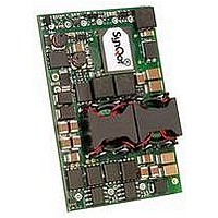
IQ65033QMA10END-G SYNQOR, IQ65033QMA10END-G Datasheet - Page 9

IQ65033QMA10END-G
Manufacturer Part Number
IQ65033QMA10END-G
Description
InQor DC/DC Converters
Manufacturer
SYNQOR
Datasheet
1.IQ65033QMA10END-G.pdf
(15 pages)
Specifications of IQ65033QMA10END-G
Dc / Dc Converter O/p Type
Fixed
No. Of Outputs
2
Input Voltage
36V To 75V
Output Voltage
5V
Output Current
10A
Output Voltage 2
3.3V
Approval Bodies
UL, CUL, TUV, IEC
Supply Voltage
48V
Lead Free Status / RoHS Status
Lead free / RoHS Compliant
Product # IQ65033QMA10
Input Enable: The ENABLE_A/B signals connect to VRTN_A/B
on the backplane via the shortest pins in the zone 1 connector.
They are the last pins to mate during board insertion, and the
first to disconnect during board extraction. The ENABLE_A and
ENABLE_B signals are diode-ORed together which lets either sig-
nal enable the module. Whenever both ENABLE pins are open,
the hot-swap switch is opened. This prevents -48V output power
from being drawn though the EARLY pre-charge resistors.
The ENABLE signals also control the management power. On
board insertion, the management power remains off until at least
one of ENABLE_A/B is connected.
management power is disabled at the end of the 100ms hold-up
period, and remains off until ENABLE_A/B is reconnected. This
prevents the IPMI controller from reading an invalid hardware
address when a board is partially inserted. Management power
flows through the EARLY pre-charge resistors for a maximum of
100ms, which provides a margin similar to the pre-charge event
in terms of resistor safe-operating-area.
EARLY Precharge Resistors: The EARLY_A/B signals connect
to the longest pins in the zone 1 power connector, and therefore
first to mate during board insertion. External resistors connected
between these signals and VRTN_A/B allow the relatively small
EMI filter capacitance to be pre-charged before the main power
pins make contact. A 100W surge rated 2010 case size resistor
is recommended (KOA SG73 series or equivalent).
Hot Swap - Thermal Shutdown: To protect the unit from
damage in an abnormal thermal environment, the hot-swap switch
will be disabled when the thermal sensor temperature rises above
the turn-off threshold. The switch will be automatically enabled
again when the temperature goes below the turn-on threshold.
The management power remains on during an over-temperature
condition.
The full featured version of the iQor reports the actual temperature
through the I
Hot Swap - Over-Current Protection: If the -48V output
current rises above the current limit threshold, the hot-swap switch
will be disabled, and will immediately enter another soft-start
sequence. If an output short is detected, the hot-swap switch
will be disabled and will enter a hiccup mode of operation with
automatic restart.
The full featured version of the iQor reports actual output current
through the I
Hot Swap - Transient Suppression: Input transient events
can occur if there is a short on an adjacent board or backplane.
The short builds up a large current in the wiring inductance,
and when a fuse blows, the voltage behind the fuse spikes very
quickly. This can cause a loss of redundancy since many other
boards could be exposed to this spike.
Technical Specification
2
2
C port.
C port.
Phone 1-888-567-9596
On board extraction, the
www.synqor.com
The iQor unit conditions the -48V output, providing for seam-
less ride-through of input voltage transients. If the positive dV/
dt of the input voltage is too high, the hot-swap switch will be
disabled and will immediately enter another soft-start sequence.
This limits the dV/dt seen on the -48V output, which prevents the
12V payload power converter from having such a large glitch
on its output that it shuts down. The -48V output hold-up function
remains active throughout, in case the hot-swap switch is forced
off for too long.
Passive Transient Suppression: Each input feed has a dedi-
cated internal bidirectional TVS zener diode, rated for a minimum
clamp voltage of 77.8V at 1mA. A TVS diode short due to electri-
cal overstress will not disable the iQor module: a fuse will open,
and the module can continue to run from the other feed.
External Hold-up Capacitor Charge: A current controlled
DC-DC converter charges the external hold-up capacitor to a volt-
age of 50V-95V, set by an external resistor. The charge voltage
can range either above or below the input feed voltage. Constant
current charging takes place whenever the hot-swap switch is
enabled.
Hold-up Capacitor Connect: When the hot-swap switch is
enabled, 2 seconds are allocated to charge the hold-up capaci-
tor. After this time, a comparator is armed, which connects the
hold-up capacitor to the -48V output should the output ever drop
below the given connect threshold. A current limit circuit protects
against damage during a short circuit condition. A dV/dt limit cir-
cuit regulates the hold-up connect switch turn-on speed. When the
comparator is tripped, the hold-up connect switch remains closed
for 100ms, is off for 2 seconds to allow the hold-up capacitor to
recharge, and then is automatically rearmed (if the output voltage
is above the given arm threshold).
Hold-up Capacitor Discharge:
switch is disabled, an internal resistor bank is connected across
the hold-up capacitor. This is intended to reduce the voltage on
the hold-up capacitor below 60V within 1 second.
Management Power:
converter delivers both 3.3V and a low power 5.0V relative
to LOGIC_GND. Over-current protection operates in constant
current with a hiccup mode if the output voltage drops too far.
Output over-voltage circuitry is included with a redundant refer-
ence and optocoupler.
Doc.# 005-IQ5033S Rev. H
Package:
Outputs:
Current:
An isolated management power
Input:
05/27/10
Whenever the hot-swap
36-75 V
5.0 V/ 3.3 V
10 A
Quarter-brick
Page 9


