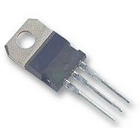
DSI 30-08A IXYS SEMICONDUCTOR, DSI 30-08A Datasheet

DSI 30-08A
Manufacturer Part Number
DSI 30-08A
Description
DIODE, STANDARD, 30A, 800V, TO220AB
Manufacturer
IXYS SEMICONDUCTOR
Datasheet
1.DSI_30-08A.pdf
(2 pages)
Specifications of DSI 30-08A
Repetitive Reverse Voltage Vrrm Max
800V
Forward Current If(av)
30A
Forward Voltage Vf Max
1.45V
Forward Surge Current Ifsm Max
300A
Operating Temperature
RoHS Compliant
Diode Type
Standard Recovery
Rectifier Diode
Symbol
I
I
I
T
T
T
M
Weight
Data according to IEC 60747 and refer to a single diode
IXYS reserves the right to change limits, test conditions and dimensions
© 2000 IXYS All rights reserved
Symbol
I
V
V
r
R
F(AV)M
FSM
2
TO-220 Outline
R
1300
1500
1700
T
V
t
VJ
VJM
stg
900
F
T0
d
thJC
V
RSM
1200
1400
1600
V
800
Conditions
T
T
V
T
V
T
V
T
V
Mounting torque
Conditions
T
I
For power-loss calculations only
T
DC current
RRM
F
V
C
VJ
VJ
VJ
VJ
R
R
R
R
VJ
VJ
= 95°C; 180° sine
= 45°C;
= 0 V;
= 150°C;
= 0 V;
= 45°C;
= 0 V;
= 150°C;
= 0 V;
= T
= 45 A; T
= T
VJM
VJM
TO-220
DSI 30-08A
DSI 30-12A
DSI 30-14A
DSI 30-16A
; V
R
VJ
= V
= 25°C
t = 10 ms (50 Hz), sine
t = 8.3 ms (60 Hz), sine
t = 10 ms (50 Hz), sine
t = 8.3 ms (60 Hz), sine
t = 10 ms (50 Hz), sine
t = 8.3 ms (60 Hz), sine
t = 10 ms (50 Hz), sine
t = 8.3 ms (60 Hz), sine
RRM
TO-263
DSI 30-08AS
DSI 30-12AS
DSI 30-14AS
DSI 30-16AS
Dim.
A
B
C
D
E
F
G
H
J
K
L
M
N
Q
12.70 14.73
14.23 16.51
Min.
9.66 10.66
3.54
5.85
2.54
1.15
0.64
4.83
3.56
0.38
2.04
0.64
Millimeter
Characteristic Values
-
-40...+150
-40...+150
Maximum Ratings
0.4...0.6
£
£
Max.
4.08
6.85
3.42
1.77
6.35
0.89
5.33
4.82
0.56
2.49
1.39
A
1.45
0.85
300
330
270
300
450
460
365
380
150
Min.
0.500 0.580
0.560 0.650
0.380 0.420
0.139 0.161
0.230 0.420
0.100 0.135
0.045 0.070
-
0.025 0.035
0.190 0.210
0.140 0.190
0.015 0.022
0.080 0.115
0.025 0.055
1.0
30
13
2
1
Inches
0.250
Max.
K/W
A
A
A
A
mW
mA
°C
°C
°C
Nm
A
A
A
A
A
g
V
V
2
2
2
2
s
s
s
s
C
V
I
TO-263 AA
TO-220 AC
A = Anode, C = Cathode, TAB = Cathode
Features
F(AV)M
TO-263 AA Outline
International standard packages
JEDEC TO-263 AA surface mountable
Planar passivated chips
Epoxy meets UL 94V-0 flammability
classification
RRM
Dim.
A
A1
b
b2
c
c2
D
D1
E
E1
e
L
L1
L2
L3
L4
R
C
A
= 800-1600 V
= 30 A
14.61
4.06
2.03
0.51
1.14
0.46
1.14
8.64
7.11
9.65
6.86
2.54
2.29
1.02
1.27
0.46
Min.
A
Millimeter
0
A
10.29
15.88
Max.
BSC
4.83
2.79
0.99
1.40
0.74
1.40
9.65
8.13
8.13
2.79
1.40
1.78
0.38
0.74
.160
.080
.020
.045
.018
.045
.340
.280
.380
.270
.100
.575
.090
.040
.050
.018
Min.
Inches
0
DSI 30
C (TAB)
Max.
BSC
C (TAB)
.190
.110
.039
.055
.029
.055
.380
.320
.405
.320
.625
.110
.055
.070
.015
.029
1 - 2
Related parts for DSI 30-08A
DSI 30-08A Summary of contents
Page 1
... TO-220 Outline Data according to IEC 60747 and refer to a single diode IXYS reserves the right to change limits, test conditions and dimensions © 2000 IXYS All rights reserved TO-263 A DSI 30-08AS DSI 30-12AS DSI 30-14AS DSI 30-16AS Maximum Ratings 30 300 330 ...
Page 2
... K/W 2 K K/W 7 K ° 100 120 140 Fig. 5 Max. forward current versus case temperature Constants for Z calculation: thJC i R (K/W) thi 1 0.01362 2 0.1962 3 0.267 4 0.3052 5 0.218 DSI30 s 10 DSI 150° ° (s) i 0.0001 0.00316 0.023 0.4 0. ...


