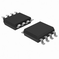
ACPL-C797-500E Avago Technologies US Inc., ACPL-C797-500E Datasheet - Page 11

ACPL-C797-500E
Manufacturer Part Number
ACPL-C797-500E
Description
Isolated Sigma-Delta, T/R+IEC+LF
Manufacturer
Avago Technologies US Inc.
Series
-r
Type
Sigma-Delta Modulatorr
Datasheet
1.ACPL-C797-000E.pdf
(16 pages)
Specifications of ACPL-C797-500E
Voltage - Isolation
5000Vrms
Input Type
DC
Voltage - Supply
3 V ~ 5.5 V, 4.5 V ~ 5.5 V
Operating Temperature
-40°C ~ 105°C
Mounting Type
Surface Mount
Package / Case
8-SOIC (0.268", 6.81mm Width)
Lead Free Status / Rohs Status
Lead free / RoHS Compliant
Available stocks
Company
Part Number
Manufacturer
Quantity
Price
Part Number:
ACPL-C797-500E
Manufacturer:
AVAGO/安华高
Quantity:
20 000
Latch-up Consideration
Latch-up risk of CMOS devices needs careful consider-
ation, especially in applications with direct connection to
signal source that is subject to frequent transient noise.
The analog input structure of the ACPL-C797 is designed
to be resilient to transients and surges, which are often
encountered in highly noisy application environments
such as motor drive and other power inverter systems.
Other situations could cause transient voltages to the
inputs include short circuit and overload conditions. The
ACPL-C797 is tested with DC voltage of up to –2 V and
2-second transient voltage of up to –6 V to the analog
inputs with no latch-up or damage to the device.
Figure 16. Modulator output vs. analog input
Table 10. Input voltage with ideal corresponding density of 1s at modulator data output, and ADC code.
Notes:
1. With bipolar offset binary coding scheme, the digital code begins with digital 0 at –FS input and increases proportionally to the analog input until
2. Ideal density of 1s at modulator data output can be calculated with V
11
Analog Input
Full-Scale Range
+Full-Scale
+Recommended Input Range
Zero
–Recommended Input Range
–Full-Scale
the full-scale code is reached at the +FS input. The zero crossing occurs at the mid-scale input.
× 65,536 + 32,768, assuming a 16-bit unsigned decimation filter.
MODULATOR OUTPUT
ANALOG INPUT
Voltage Input
640 mV
+320 mV
+200 mV
0 mV
–200 mV
–320 mV
IN
+FS (ANALOG INPUT)
0 V (ANALOG INPUT)
–FS (ANALOG INPUT)
TIME
/640 mV + 50%; similarly, the ADC code can be calculated with (V
Modulator Data Output
Input signal information is contained in the modulator
output data stream, represented by the density of ones
and zeros. The density of ones is proportional to the input
signal voltage, as shown in Figure 16. A differential input
signal of 0 V ideally produces a data stream of ones and
zeros in equal densities. A differential input of –200 mV
corresponds to 18.75% density of ones, and a differential
input of +200 mV is represented by 81.25% density of
ones in the data stream. A differential input of +320 mV or
higher results in ideally all ones in the data stream, while
input of –320 mV or lower will result in all zeros ideally.
Table 10 shows this relationship.
Density of 1s
100%
81.25%
50%
18.75%
0%
ADC Code
(16-bit unsigned decimation)
65,535
53,248
32,768
12,288
0
IN
/640 mV)


