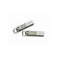
AFBR-5701ALZ Avago Technologies US Inc., AFBR-5701ALZ Datasheet - Page 2

AFBR-5701ALZ
Manufacturer Part Number
AFBR-5701ALZ
Description
MMGbE SFPw/oDMI StdLatch I-tmpRoHS
Manufacturer
Avago Technologies US Inc.
Datasheet
1.AFBR-5701LZ.pdf
(22 pages)
Specifications of AFBR-5701ALZ
Data Rate
1.25Gbps
Wavelength
850nm
Applications
Ethernet
Voltage - Supply
3.135 V ~ 3.465 V
Connector Type
LC Duplex
Mounting Type
SFP
Product
Transceiver
Maximum Rise Time
220 ps, 260 ps
Maximum Fall Time
220 ps, 260 ps
Pulse Width Distortion
0.227 ns, 0.266 ns
Operating Supply Voltage
3.135 V to 3.465 V
Maximum Operating Temperature
+ 85 C
Minimum Operating Temperature
- 40 C
Package / Case
SFP-20
Function
Diagnostic Monitoring Interface
Lead Free Status / RoHS Status
Lead free / RoHS Compliant
For Use With
Multimode Glass
Lead Free Status / RoHS Status
Lead free / RoHS Compliant
Figure 1. SFP Block Diagram
Overview
The AFBR-570 Z family of optical transceivers are
compliant with the specifications set forth in the
IEEE802.3 (1000BASE-SX), Fibre Channel (100-M5-SN-I,
100-M6-SN-I), and the Small Form-Factor Pluggable
(SFP) Multi-Source Agreement (MSA). This family of
transceivers is qualified in accordance with Telcordia
GR-468-CORE. Its primary application is servicing Gigabit
Ethernet and Fibre Channel links between optical
networking equipment.
The AFBR-570 Z offers maximum flexibility to designers,
manufacturers, and operators of Gigabit Ethernet
networking equipment. A pluggable architecture allows the
module to be installed into MSA standard SFP ports at any
time – even with the host equipment operating and online.
This facilitates the rapid configuration of equipment to
precisely the user’s needs – reducing inventory costs and
network downtime. Compared with traditional transceivers,
the size of the Small Form Factor package enables higher
port densities.
Module Diagrams
Figure 1 illustrates the major functional components of the
AFBR-570 Z. The external configuration of the module is
depicted in Figure 7. Figure 8 depicts the panel and host
board footprints.
2
OPTICAL INTERFACE
LIGHT FROM FIBER
LIGHT TO FIBER
RECEIVER
TRANSMITTER
PHOTO-DETECTOR
VCSEL
CONTROLLER & MEMORY
AMPLIFICATION
& QUANTIZATION
Figure 2. Pin description of the SFP electrical interface.
20
19
18
17
16
15
14
13
12
11
V
TD–
TD+
V
V
V
V
RD+
RD–
V
EE
EE
CC
CC
EE
EE
CIRCUITRY
TOP OF BOARD
DRIVER &
T
T
R
R
T
R
SAFETY
LASER
3 2 1
ENGAGEMENT
SEQUENCE
RD+ (RECEIVE DATA)
RD— (RECEIVE DATA)
Rx LOSS OF SIGNAL
MOD-DEF2 (SDA)
MOD-DEF1 (SCL)
MOD-DEF0
TX_DISABLE
TD+ (TRANSMIT DATA)
TD— (TRANSMIT DATA)
TX_FAULT
ELECTRICAL INTERFACE
(AS VIEWED THROUGH TOP OF BOARD)
10
1
2
3
4
5
6
7
8
9
BOTTOM OF BOARD
V
TX FAULT
TX DISABLE
MOD-DEF(2)
MOD-DEF(1)
MOD-DEF(0)
RATE SELECT
LOS
V
V
EE
EE
EE
T
R
R
3 2 1


