AFBR-703SDDZ Avago Technologies US Inc., AFBR-703SDDZ Datasheet - Page 15
AFBR-703SDDZ
Manufacturer Part Number
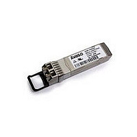
AFBR-703SDDZ
Description
SFP+ 850nm 1/10GbE SR MMF,Gen2 STD
Manufacturer
Avago Technologies US Inc.
Series
-r
Datasheet
1.AFBR-703SDDZ.pdf
(22 pages)
Specifications of AFBR-703SDDZ
Data Rate
10.312Gbd
Wavelength
850nm
Applications
Ethernet
Voltage - Supply
3.135 V ~ 3.465 V
Connector Type
LC Duplex
Mounting Type
SFP+
Optical Fiber Type
TX/RX
Data Transfer Rate
10313MBd
Optical Rise Time
0.028ns
Optical Fall Time
0.028ns
Operating Temperature Classification
Commercial
Peak Wavelength
860nm
Package Type
SFP
Operating Supply Voltage (min)
3.135V
Operating Supply Voltage (typ)
3.3V
Operating Supply Voltage (max)
3.465V
Output Current
20mA
Operating Temp Range
0C to 70C
Mounting
Snap Fit To Panel
Pin Count
20
Lead Free Status / RoHS Status
Lead free / RoHS Compliant
Lead Free Status / RoHS Status
Lead free / RoHS Compliant


Table 12. Control Functions: Two-Wire Interface Timing Characteristics
The following characteristics are defined over the Recommended Operating Conditions unless otherwise noted.
Parameter
TX_DISABLE Assert Time
TX_DISABLE Negate Time
TX_FAULT Assert Time
Rx_LOS Assert Time
Rx_LOS Deassert Time
Analog parameter data ready
Two-Wire Interface Ready
Write Cycle Time Parameter
Two-Wire Interface Clock Rate
Time bus free before new
transmission can start
Notes:
1. Time from two-wire interface assertion of TX_DISABLE (A2h, byte 110, bit 6) to when the optical output falls below 10% of nominal. Measured
2. Time from two-wire interface de-assertion of TX_DISABLE (A2h, byte 110, bit 6) to when the modulated optical output rises above 90% of
3. Time from fault to two-wire interface TX_FAULT (A2h, byte 110, bit 2) asserted.
4. Time for two-wire interface assertion of Rx_LOS (A2h, byte 110, bit 1) from loss of optical signal.
5. Time for two-wire interface de-assertion of Rx_LOS (A2h, byte 110, bit 1) from presence of valid optical signal.
6. From power on to data ready bit asserted (A2h, byte 110, bit 0). Data ready indicates analog monitoring circuitry is functional.
7. Time from power on until module is ready for data transmission over the two-wire interface (reads or writes over A0h and A2h).
8. Time from stop bit to completion of a 1-8 byte write command. Measured from the stop bit, for a one t om four byte write the maximum cycle
9. Between STOP and START. See SFF 8431 Section 4.3
15
from falling clock edge after stop bit of write transaction.
nominal.
time is 40ms and for a five to eight byte write the maximum cycle time is 80ms.
Symbol
t_off_twi
t_on_twi
t_fault_twi
t_loss_on_twi
t_loss_off_twi
t_data
t_serial
t_write
f_serial_clock
t_buf
Minimum
20
Maximum
100
100
100
100
100
1000
300
80
400
Unit
ms
ms
ms
ms
ms
ms
ms
ms
kHz
Ps
Note 7
Notes
Note 1
Note 2
Note 3
Note 4
Note 5
Note 6
Note 8
Note 9
Related parts for AFBR-703SDDZ
Image
Part Number
Description
Manufacturer
Datasheet
Request
R

Part Number:
Description:
TXRX ETHERNET 125MBD MMF 2X5
Manufacturer:
Avago Technologies US Inc.
Datasheet:

Part Number:
Description:
TXRX OPT XFP 10GB/S 850NM
Manufacturer:
Avago Technologies US Inc.
Datasheet:

Part Number:
Description:
TXRX OPT 1X9 100MBPS DUPLEX SC
Manufacturer:
Avago Technologies US Inc.
Datasheet:

Part Number:
Description:
TXRX OPT 1X9 100MBPS DUPLEX ST
Manufacturer:
Avago Technologies US Inc.
Datasheet:

Part Number:
Description:
TXRX OPT 1X9 100MBPS DUPL ST SIP
Manufacturer:
Avago Technologies US Inc.
Datasheet:

Part Number:
Description:
TXRX OPT 1X9 100MBPS DUPL SC SIP
Manufacturer:
Avago Technologies US Inc.
Datasheet:

Part Number:
Description:
TXRX OPT 1X9 100MBPS DUPL ST SIP
Manufacturer:
Avago Technologies US Inc.
Datasheet:

Part Number:
Description:
TXRX ATM SONET OC3 3V SC 1X9
Manufacturer:
Avago Technologies US Inc.
Datasheet:
Part Number:
Description:
TXRX ATM/SONET OC-3 2X5
Manufacturer:
Avago Technologies US Inc.
Datasheet:

Part Number:
Description:
TXRX 127MBD DUPLEX SC 1X9
Manufacturer:
Avago Technologies US Inc.
Datasheet:

Part Number:
Description:
OPTOCOUPLER GATE DRV 2A 16-SOIC
Manufacturer:
Avago Technologies US Inc.
Datasheet:
Part Number:
Description:
OPTOCOUPLER 2CH 2.5A 16-SOIC
Manufacturer:
Avago Technologies US Inc.
Datasheet:

Part Number:
Description:
OPTOCOUPLER GATE DRV 0.4A 16SOIC
Manufacturer:
Avago Technologies US Inc.
Datasheet:

Part Number:
Description:
OPTOCOUPLER 2.0A 250KHZ 8-DIP
Manufacturer:
Avago Technologies US Inc.
Datasheet:

Part Number:
Description:
OPTOCOUPLER 2.0A 250KHZ GW 8-SMD
Manufacturer:
Avago Technologies US Inc.
Datasheet: