AMMP-6408-TR1G Avago Technologies US Inc., AMMP-6408-TR1G Datasheet - Page 7
AMMP-6408-TR1G
Manufacturer Part Number
AMMP-6408-TR1G
Description
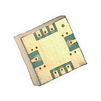
Power Amp, MMIC, 6-18GHz Pkg
Manufacturer
Avago Technologies US Inc.
Specifications of AMMP-6408-TR1G
Current - Supply
650mA
Frequency
6GHz ~ 18GHz
Gain
18dB
P1db
28.5dBm
Package / Case
8-SMD
Rf Type
LMDS, MMDS
Test Frequency
8GHz
Voltage - Supply
6V
Manufacturer's Type
Power Amplifier
Number Of Channels
1
Supply Current
650@5VmA
Frequency (max)
18GHz
Operating Supply Voltage (max)
6V
Package Type
SMT
Mounting
Surface Mount
Pin Count
8
Lead Free Status / RoHS Status
Lead free / RoHS Compliant
Noise Figure
-
Lead Free Status / Rohs Status
Compliant


Biasing and Operation
The recommended quiescent DC bias condition for
optimum efficiency, performance, and reliability is
Vdd = 5 volts with Vg set for Idd = 650 mA. Minor im-
provements in performance are possible depending on
the application. The drain bias voltage range is 3 to 5 V .
A single DC gate supply connected to Vg will bias all gain
stages. Muting can be accomplished by setting Vgg to
the pinch-off voltage Vp.
A simplified schematic for the AMMP6408 MMIC die is
shown in Figure 7. The MMIC die contains ESD and over
voltage protection diodes for Vg, Vd, and Vd2 terminals.
In a finalized package form, Vd and Vd2 terminals are
commonly connected to the Vdd terminal. The package
diagram for the recommended assembly is shown in
Figure 8. In finalized package form, ESD diodes protect
all possible ESD or over voltage damages between Vgg
and ground, Vgg and Vdd, Vdd and ground. Typical ESD
diode current versus diode voltage for -connected
diodes in series is shown in Figure 3. Under the recom-
mended DC quiescent biasing condition at Vds = 5 V ,
Ids = 650 mA, Vgg = - V , typical gate terminal current is
approximately 0.3mA. If an active biasing technique is
selected for the AMMP6408 MMIC PA DC biasing, the
active biasing circuit must have more than 0-times
higher internal current that the gate terminal current.
7
An optional output power detector network is also pro-
vided. A typical measured detector voltage versus out-
put power at 8 GHz is shown Figure 20. The differential
voltage between the Det-Ref and Det-Out pads can be
correlated with the RF power emerging from the RF out-
put port. The detected voltage is given by,
V = (V
where V
age at the DET _O port, and V
offset voltage. There are three methods to calculate V
. V
2. V
3. V
The RF ports are AC coupled at the RF input to the first
stage and the RF output of the final stage. No ground
wired are needed since ground connections are made
with plated through-holes to the backside of the device.
ment (by removing or switching off the power source
and measuring V
due to temperature drift of less than 0.0 dB/50°C.
ture. The drift error will be less than 0.25 dB.
stored in a lookup table, or it can be measured at two
temperatures and a linear fit used to calculate V
any temperature. This method gives an error close to
the method #.
ofs
ofs
ofs
ref
can be measured before each detectore measure-
can either be characterized over temperature and
can be measured at a single reference tempera-
– V
ref
is the voltage at the DET _R port, V
det
) – V
ofs
ref
– V
det
). This method gives an error
ofs
is the zero-input-power
det
is a volt-
ofs
ofs
at
:
Related parts for AMMP-6408-TR1G
Image
Part Number
Description
Manufacturer
Datasheet
Request
R

Part Number:
Description:
Power Amp, MMIC, 6-18GHz Pkg
Manufacturer:
Avago Technologies US Inc.
Datasheet:

Part Number:
Description:
Power Amp, MMIC, 6-18GHz Pkg
Manufacturer:
Avago Technologies US Inc.
Datasheet:

Part Number:
Description:
IC AMP GP HI PWR 6-20GHZ 8-SMD
Manufacturer:
Avago Technologies US Inc.
Datasheet:

Part Number:
Description:
IC AMP GP HI PWR 6-20GHZ 8-SMD
Manufacturer:
Avago Technologies US Inc.
Datasheet:

Part Number:
Description:
IC MMIC AMP HGA 6-20GHZ 8SMD
Manufacturer:
Avago Technologies US Inc.
Datasheet:

Part Number:
Description:
IC MMIC AMP HGA 6-20GHZ 8SMD
Manufacturer:
Avago Technologies US Inc.
Datasheet:
Part Number:
Description:
IC MMIC LOW NOISE 6-20GHZ 8-SMD
Manufacturer:
Avago Technologies US Inc.
Datasheet:
Part Number:
Description:
IC AMP GP HI PWR 6-20GHZ 8-SMD
Manufacturer:
Avago Technologies US Inc.
Datasheet:

Part Number:
Description:
6-20 GHz High Gain Amp In SMT Pkg
Manufacturer:
Avago Technologies US Inc.
Datasheet:

Part Number:
Description:
LNA IR Mixer 6-22GHz Package
Manufacturer:
Avago Technologies US Inc.
Datasheet:

Part Number:
Description:
OPTOCOUPLER GATE DRV 2A 16-SOIC
Manufacturer:
Avago Technologies US Inc.
Datasheet:
Part Number:
Description:
OPTOCOUPLER 2CH 2.5A 16-SOIC
Manufacturer:
Avago Technologies US Inc.
Datasheet:

Part Number:
Description:
OPTOCOUPLER GATE DRV 0.4A 16SOIC
Manufacturer:
Avago Technologies US Inc.
Datasheet:

Part Number:
Description:
OPTOCOUPLER 2.0A 250KHZ 8-DIP
Manufacturer:
Avago Technologies US Inc.
Datasheet:

Part Number:
Description:
OPTOCOUPLER 2.0A 250KHZ GW 8-SMD
Manufacturer:
Avago Technologies US Inc.
Datasheet: