119152-52 AMETEK, 119152-52 Datasheet
119152-52
Manufacturer Part Number
119152-52
Description
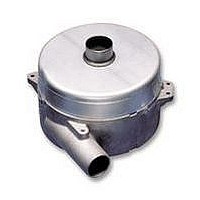
BLOWER, 145MM, 240V, 1200W
Manufacturer
AMETEK
Series
Windjammerr
Type
Canisterr
Specifications of 119152-52
External Height
160.02mm
Current Type
AC
Supply Voltage
240VAC
Current Rating
5A
Flow Rate
90l/s
Power Connection Type
Pins
Depth
128.77mm
External Length / Height
160.02mm
Flow
RoHS Compliant
Air Flow
203 CFM
Brand/series
IntelliGen™
Configuration
Bypass
Controls
Mechanical
Current, Rating
10 A
Diameter, Inlet
1.75 "
Diameter, Outlet
1.75 "
Dimensions
145Dia x 130.3L mm
Power, Rating
1200 W
Special Features
Speed Control
Static Pressure
64 in.-H2O
Temperature, Operating, Maximum
+50 °C
Temperature, Operating, Minimum
0 °C
Termination
Terminals
Voltage, Rating
240 VAC
Weight
6 lbs.
Outer Diameter
145mm
Flow Rate - Imperial
190cu.ft/min
Flow Rate - Metric
522m3/h
Rohs Compliant
Yes
External Depth
128.77mm
Lead Free Status / Rohs Status
RoHS Compliant part


64
5.7” (145mm) DC Bypass Blower
1200 Watt, 240 Volt High Flow – IntelliGen
* These part numbers are available through AMETEK Technical & Industrial Products’ distributors.
NOTES:
OPERATING PARAMETERS:
• Input Voltage Range: 240 Volt AC Models: 208 to 264 VAC RMS, 50/60 Hz, single phase, maximum running current 10 Amps RMS.
• Isolated Speed Control:
• Speed Control Input Current: Less than 20 mA at 10 Volts input with multi turn internal potentiometer set to minimum (fully counter-clockwise).
• Speed Control Drift with Temperature:
• Operating Temperature: 0°C to 50°C.
• Storage Temperature: -40°C to 85°C.
• Dielectric Testing: 1500 Volts AC RMS 60 Hz applied for one second between input pins and ground, 3mA leakage max.
• Approximate Weight: 6 lbs.
Stages
Vacuum, Maximum
(Sealed Vacuum)
Pressure, Maximum
(Sealed Pressure)
Flow Rate, Maximum
(Open Flow)
Inlet/Outlet Diameter
(Dimension “D” above)
Length
(Dimension “I” above)
Length
(Dimension “L” above)
Note: Although this unit contains a lockout feature that detects low voltage conditions, the electronics should not be operated continuously below the input
voltage range listed above.
Analog Input Voltage Range: 2.2 to +10 VDC nominal, (+12 VDC maximum).
Digital Pulse Input: 400 Hz to 20 KHz, 0 to +10 Volt pulse nominal, minimum duty cycle 10%, 0 to +12 Volt maximum.
Note: Setting of potentiometer can affect control voltage range and maximum speed can be reached before reaching 10 VDC.
Analog Mode: Typ. +/-4% from nominal speed at +23°C.
Digital or Direct Mode: Typ. +/-4% from nominal speed at +23°C.
Note: Internal electronic controller is thermally protected.
(70.87±2.03)
INCH
(MM)
SEE DETAIL
“E”
2.79±.08
Blower Data
-B-
CONTROL
54°30'±2°
SPEED
OR
L C
“M”
26°±2°
ACCESS FOR
MECHANICALLY
ADJUSTED SPEED
SEE VIEW
33°
(60.97)
2.40
CONTROL
VIEW
“B”
(35.05)
REF.
1.38
“B”
EXHAUST
Unit of Measure
AIR
USE THIS HOLE FOR
GROUNDING OR EARTHING.
REFER TO APPROPRIATE
LISTING OR REGULATORY
AGENCY FOR PROPER
METHOD OF GROUNDING
OR EARTHING.
LOCATED AS SHOWN ON
Ø
(1) Ø
Ø
(66.04)
(162.56)
(83.57±1.52)
Ø.024/(.61) A
2.60
6.400
.168±.003
(4.27±.07)
3.29±.06
in. H
in. H
inches
inches
inches
mBar
mBar
m
CFM
MAX.
mm
mm
mm
—
BOLT CIRCLE.
3
/hr
2
2
O
O
HOLE THRU,
M
S
™
119152 M*
119151 E*
(26.42)
1.04
Ø.015/(.38)
130.30
44.45
11.94
1.75
5.13
137
159
203
345
“L”
.47
55
64
1
-B-
High Flow
“I”
(1.3)
.05
119154 M*
119153 E*
INTAKE
-A-
1
2
3
4
5
MAX. BOW TYP.
BOTH ENDS
157.23
(22.35±3.3)
AIR
44.45
36.86
1.75
1.58
6.19
POST HEADER ASSEMBLY
229
111
276
160
272
Ø
.88±.13
DETAIL
92
2
(149.4)
5.88
Part Number
GROUND (
NOT USED
NOT USED
AC INPUT VOLTAGE
“M”
"D"
MAX.
2
"D"
)
1
119156 E
(95.0)
3.74
182.11
44.45
30.23
1
2
3
4
5
1.75
1.19
7.17
119
296
140
348
137
233
3
(3) Ø
LOCATED AS SHOWN ON A
Ø
45°
POST HEADER ASSEMBLY
(165.1)
DETAIL
6.500
LOW (-)
HIGH (+)
GROUND (
AC INPUT VOLTAGE
(.4.27±.07)
.168±.003
Ø.024/.61 A
BOLT CIRCLE.
“E”
}
ISOLATED SPEED
CONTROL INPUT
(2X)
90°
HOLES THRU,
)
M
Ultra Flow
69.85/63.50
119155 E*
2.75/2.50
S
136.40
18.03
5.37
104
117
274
466
.71
42
47
1
Related parts for 119152-52
Image
Part Number
Description
Manufacturer
Datasheet
Request
R

Part Number:
Description:
BLOWER, 145MM, 120V, 250W
Manufacturer:
AMETEK
Datasheet:
Part Number:
Description:
BLOWER, 145MM, 240V, 1200W
Manufacturer:
AMETEK
Datasheet:
Part Number:
Description:
BLOWER, 145MM, 240V, 400W
Manufacturer:
AMETEK
Datasheet:
Part Number:
Description:
BLOWER, 145MM, 240V, 400W
Manufacturer:
AMETEK
Datasheet:
Part Number:
Description:
BLOWER, 145MM, 240V, 400W
Manufacturer:
AMETEK
Datasheet:
Part Number:
Description:
BLOWER, 145MM, 240V, 400W
Manufacturer:
AMETEK
Datasheet:
Part Number:
Description:
BLOWER, 145MM, 240V, 1200W
Manufacturer:
AMETEK
Datasheet:

Part Number:
Description:
BLOWER, 76MM, 12VDC
Manufacturer:
AMETEK
Datasheet:
Part Number:
Description:
BLOWER, 76MM, 24VDC
Manufacturer:
AMETEK
Datasheet:

Part Number:
Description:
BLOWER, 127MM, 24VDC, INT, HF
Manufacturer:
AMETEK
Datasheet:
Part Number:
Description:
BLOWER, 145MM, 120V, 250W
Manufacturer:
AMETEK
Datasheet:

Part Number:
Description:
24 Volt Brushless DC Motor Controller
Manufacturer:
AMETEK
Datasheet:
Part Number:
Description:
24 Volt Brushless DC Motor Controller
Manufacturer:
AMETEK
Datasheet:
Part Number:
Description:
11-52 VDC BRUSHLESS DC MOTOR CONTROLLER
Manufacturer:
AMETEK
Datasheet:
Part Number:
Description:
RELEASE BAR SPRING / 119-0000-011
Manufacturer:
C&K Components
119152-52 Summary of contents
Page 1
... S 1.04 (26.42) USE THIS HOLE FOR GROUNDING OR EARTHING. REFER TO APPROPRIATE LISTING OR REGULATORY AGENCY FOR PROPER METHOD OF GROUNDING Ø.015/(.38) OR EARTHING. -B- “L” 3.29±.06 (83.57±1.52) “B” Unit of Measure 119152 M* 119151 E* — mBar 137 in mBar 159 CFM 203 ...
Page 2
... AMETEK BLDC motor controllers. Actual performance will vary depending on the operating environment and application. AMETEK products are not designed for and should not be used in medical life support applications. AMETEK reserves the right to revise its products without notifi ...