SK-POWER-3P-LV-MC Fujitsu, SK-POWER-3P-LV-MC Datasheet - Page 15
SK-POWER-3P-LV-MC
Manufacturer Part Number
SK-POWER-3P-LV-MC
Description
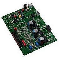
Low Voltage/Motor Control Evaluation Board
Manufacturer
Fujitsu
Datasheet
1.SK-POWER-3P-LV-MC.pdf
(23 pages)
Specifications of SK-POWER-3P-LV-MC
Silicon Manufacturer
Fujitsu
Silicon Core Number
SK-91470-144PMC1-MC, SK-91480-100PMC-MC
Kit Application Type
Power Management - Motor Control
Lead Free Status / RoHS Status
Contains lead / RoHS non-compliant


SK-POWER-3P-LV User Guide
4 Connectors
4.1 Power connector (X15)
The following figure shows the power connection jack X15. This connector is used to
connect an external unregulated DC power supply voltage (9-15V DC, depending e.g. on
gate driver configuration) to the evaluation board.
Shield is connected to GND (-)
Connector X15:
Center is connected to pos. supply (+)
It is recommended to use 12V input voltage (depending e.g. on gate driver configuration) to
keep the power dissipation to a minimum.
4.2 DC link power connector (X11)
The DC link power can be supplied either by X15 (when JP18 and JP19 are set and
the current is not higher than 3A) or by X11. X11 is a screw terminal for currents up
to 15A. Be aware that there is no protection diode for this input on the board. The
voltage input range depends on the jumper settings as described in chapter 3.1.
It is recommended to use an external protection diode with sufficient current
capability in case the used power supply is not protected against reverse current
sourced from the load flowing into the power supply.
Further, it is strongly recommended to use a laboratory DC power supply with
adjustable current limitation with this board. Otherwise, in case of software or
hardware malfunctions or false configurations, high currents can flow and damage
the power supply and/or the board and lead to overheating by excessive power
dissipation.
4.3 Brake resistor connector (X10)
The board provides a power transistor which can act as braking chopper. This kind
of circuit is used to dissipate energy which is generated when the motor works as
generator. This can happen, if the motor quickly decelerates with a heavy load or if
the motor is moved by the load. In this case, the DC link voltage rises, because the
link capacitors have to store the energy. To avoid over-voltage, a resistor can be
used to soak this energy from the DC link. The value and power rating depends on
the DC link voltage, the possible current generated by the motor and load, and the
duty cycle in which braking can occur. The braking current should not exceed 6A in
average and 15A peak to limit power dissipation of T7. Also, the switching frequency
for T7 should not exceed 2-3kHz to limit switching losses, especially at higher
braking currents (low resistance, high voltage). T7 can be driven at 100% duty cycle
(no bootstrap circuit).
© Fujitsu Microelectronics Europe GmbH
- 15 -
Related parts for SK-POWER-3P-LV-MC
Image
Part Number
Description
Manufacturer
Datasheet
Request
R

Part Number:
Description:
KIT, STARTER, JADE-L, MB86R03
Manufacturer:
Fujitsu
Datasheet:
Part Number:
Description:
Fujitsu Media Devices Limited [NMOS 1- CHANNEL, 13-BIT AND 3-CHANNEL, 6-BIT D/A CONVERTER]
Manufacturer:
Fujitsu
Datasheet:
Part Number:
Description:
Fujitsu Media Devices Limited [32-bit RISC Microcontroller]
Manufacturer:
Fujitsu
Datasheet:
Part Number:
Description:
Fujitsu Media Devices Limited [MOS 262,144 BIT DYNAMIC RANDOM ACCESS MEMORY]
Manufacturer:
Fujitsu
Datasheet:
Part Number:
Description:
Fujitsu Media Devices Limited [PROGRAMMABLE TIMER]
Manufacturer:
Fujitsu
Datasheet:
Part Number:
Description:
Fujitsu Media Devices Limited [MOS Universal Asynchronous receiver/transmitter(UART)]
Manufacturer:
Fujitsu
Datasheet:
Part Number:
Description:
Fujitsu Media Devices Limited [16M (2M X 8/1M X 16) BIT]
Manufacturer:
Fujitsu
Datasheet:
Part Number:
Description:
KIT, STARTER, MB95200/210/220
Manufacturer:
Fujitsu
Datasheet:
Part Number:
Description:
SWITCHING REGULATOR CONTROLLER
Manufacturer:
Fujitsu
Datasheet:
Part Number:
Description:
QUAD OPERATIONAL AMPLIFIER
Manufacturer:
Fujitsu
Datasheet:
Part Number:
Description:
Switching Regulator Controller (Switchable between push-pull and single-end functions)
Manufacturer:
Fujitsu
Datasheet:
Part Number:
Description:
HIGH-SPEED CMOS SINGLE CHIP 4-BIT MICROCOMPUTER MB88505HHIGH-SPEED CMOS SINGLE CHIP 4-BIT MICROCOMPUTER
Manufacturer:
Fujitsu
Datasheet:
Part Number:
Description:
MOS 1024 BIT NON VOLATILE RANDOM ACCESS MEMORY
Manufacturer:
Fujitsu
Datasheet:
Part Number:
Description:
Schottky TTL 2048-Bit Bipolar Programmable Read-Only Memory
Manufacturer:
Fujitsu
Datasheet: