HFBR-0555 Avago Technologies US Inc., HFBR-0555 Datasheet
HFBR-0555
Specifications of HFBR-0555


Related parts for HFBR-0555


HFBR-0555 Summary of contents
Page 1
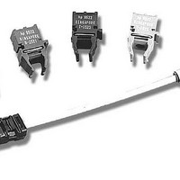
... These transceivers are all supplied in the new industry standard DIP style with a MT-RJ fiber connector interface. ATM 2 km Backbone Links The HFBR-5905 is a 1300 nm product with optical performance compliant with the SONET STS-3c (OC-3) Physical Layer Interface Specification. This physical layer is defined in the ATM Forum User-Network Interface (UNI) Specification Version 3 ...
Page 2
... IC which converts differential PECL logic signals, ECL referenced (shifted +3.3 V supply, into an analog LED drive current. Receiver Sections The receiver section of the HFBR-5905 utilizes an InGaAs PIN photodiode coupled to a custom silicon transimpedance preamplifier IC packaged in the optical subassembly portion of the receiver. ...
Page 3
OVERALL RECEPTACLE CENTER LINE) Case temperature measurement point 9.6 13.59 (0.378) (0.535) MAX. MAX. 12 (0.472) 9.3 9.8 (0.366) (0.386) MAX. MAX. Ø 1.07 (0.042) DIMENSIONS IN MILLIMETERS (INCHES) NOTES: 1. THIS PAGE DESCRIBES THE MAXIMUM ...
Page 4
RX TX Top View RECEIVER SIGNAL GROUND 1 o RECEIVER POWER SUPPLY SIGNAL DETECT 3 o RECEIVER DATA OUT BAR 4 o RECEIVER DATA OUT 5 Figure 3. Pin Out Diagram. Pin Descriptions: Pin 1 Receiver Signal ...
Page 5
... The area under the curves represents the remaining OPB at any link length, which is available for overcoming non-fiber cable related losses. 12 HFBR-5905, 62.5/125 µ HFBR-5905 50/125 µm 6 ...
Page 6
... Data rate (bits/sec) is the symbol rate divided by the encoding factor used to encode the data (symbols/ bit). When used in 155 Mb/s SONET OC-3 applications the performance of the 1300 nm transceivers, HFBR-5905 is guaranteed to the full conditions listed in product specification tables. The transceivers may be used for other applications at signaling rates different than 155 Mb/s with some variation in the link optical power budget ...
Page 7
Board Layout - Decoupling Circuit, Ground Planes and Termination Circuits It is important to take care in the layout of your circuit board to achieve optimum performance from these transceivers. Figure 7 provides a good example of a schematic for ...
Page 8
Note 100 nF Figure 8. Alternative Termination Circuits 7.11 Ø 1.4 ±0.1 (0.28) (0.055 KEEP OUT AREA ...
Page 9
... For additional information regarding EMI, susceptibility, ESD and conducted noise testing procedures and results on the Transceiver family, please refer to Applications Note 1075, Testing and Measuring Electro- magnetic Compatibility Performance of the HFBR-510X/- 520X Fiber Optic Transceivers. Performance Meets Class 2 (2000 to 3999 Volts). ...
Page 10
... TRANSMITTER OUTPUT OPTICAL RISE/FALL C TIMES – ns HFBR-5905 TRANSMITTER TEST RESULTS OF λ , ∆λ AND t ARE CORRELATED AND COMPLY C r/f WITH THE ALLOWED SPECTRAL WIDTH AS A FUNCTION OF CENTER WAVELENGTH FOR VARIOUS RISE AND FALL TIMES. ...
Page 11
... Recommended Operating Conditions Parameter Ambient Operating Temperature HFBR-5905 HFBR-5905A Supply Voltage Data Input Voltage - Low Data Input Voltage - High Data and Signal Detect Output Load Differential Input Voltage (p-p) Notes: A. Ambient Operating Temperature corresponds to transceiver case temperature of 0 °C mininum to +85 °C maximum with necessary airflow applied. Recommanded case temperature measurement point can be found in Figure 2. B. Ambient Operating Temperature corresponds to transceiver case temperature of -40 ° ...
Page 12
... Systematic Jitter Contributed by the Transmitter Random Jitter Contributed by the Transmitter Receiver Optical and Electrical Characteristics HFBR-5905 (T = 0°C to +70° HFBR-5905A (T = -40°C to +85° Parameter Input Optical Power Minimum at Window Edge Input Optical Power Minimum at Eye Center Input Optical Power Maximum ...
Page 13
... Avago Technologies will incorporate this requirement into the specifications for these 13 products defined. The HFBR-5905 products typically comply with the template requirements of CCITT (now ITU-T) G.957 Section 3.2.5, Figure 2 for the STM-1 rate, excluding the optical -2 V ...
Page 14
For product information and a complete list of distributors, please go to our web site: Avago, Avago Technologies, and the A logo are trademarks of Avago Technologies, Limited in the United States and other countries. Data subject to change. Copyright ...