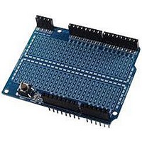
AMICUS18-COMPANION-SHIELD AMICUS, AMICUS18-COMPANION-SHIELD Datasheet - Page 43

AMICUS18-COMPANION-SHIELD
Manufacturer Part Number
AMICUS18-COMPANION-SHIELD
Description
Amicus18 Companion Shield
Manufacturer
AMICUS
Datasheet
1.AMICUS18-COMPANION-SHIELD.pdf
(49 pages)
Specifications of AMICUS18-COMPANION-SHIELD
Silicon Manufacturer
Microchip
Core Architecture
PIC
Core Sub-architecture
PIC18
Features
USB Interface, In Circuit Serial Programming Interface
Kit Contents
Board
Silicon Family Name
PIC
Silicon Core Number
PIC18F25K20
Rohs Compliant
Yes
Lead Free Status / RoHS Status
Lead free / RoHS Compliant
For Use With
PIC18F25K20 Microcontroller
Digital Meets Analogue
Sometimes the microcontroller needs to interface back to the real world with an analogue result. This is
termed Digital to Analogue Conversion, or DAC. This can be performed several ways; by using a dedi-
cated DAC peripheral device, by using a digital resistor device, or by using Pulse Width Modulation
(PWM). PWM is the method that is built into the Amicus18’s microcontroller, and requires no specialised
devices to be used, so we’ll discuss this method here.
Pulse Width Modulation (PWM)
Pulse Width Modulation fakes a voltage by producing a series of pulses at regular intervals, and varying
the width of the pulses. The resulting average voltage is the result of the pulse widths. The Amicus18’s
microcontroller can produce a high voltage of 3.3 Volts and low of 0 Volts.
In the illustration below, the pin is pulsed high for the same length of time as it is pulsed low. The time
the pin is high (called the pulsewidth) is about half the total time it takes to go from low to high to low
again. This ratio is called the duty cycle. When the duty cycle is 50%, the average voltage is about half
the total voltage. i.e. 1.6 Volts.
If the duty cycle is made less than 50% by pulsing on for a shorter amount of time, a lower effective
voltage is produced:
If the duty cycle is made greater than 50% by pulsing on for a longer amount of time, a higher effective
voltage is produced:
In order to create a constant voltage instead of a series of pulses, we need a simple RC low pass filter.
As it’s name suggests this consists of a Resistor and a Capacitor.
A filter is a circuit that allows voltage changes of only a certain frequency range to pass. For example, a
low-pass filter would block frequencies above a certain range. This means that if the voltage is changing
more than a certain number of times per second, these changes would not make it past the filter, and
only an average voltage would be seen.
Crownhill AssociatesLimited 2009 - All Rights Reserved
Amicus18 Companion Shield
Version 1.0
Time
Time
Time
42
Effective Voltage
Effective Voltage
Effective Voltage
06-10-2009


