AMICUS18-COMPANION-SHIELD AMICUS, AMICUS18-COMPANION-SHIELD Datasheet - Page 8
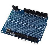
AMICUS18-COMPANION-SHIELD
Manufacturer Part Number
AMICUS18-COMPANION-SHIELD
Description
Amicus18 Companion Shield
Manufacturer
AMICUS
Datasheet
1.AMICUS18-COMPANION-SHIELD.pdf
(49 pages)
Specifications of AMICUS18-COMPANION-SHIELD
Silicon Manufacturer
Microchip
Core Architecture
PIC
Core Sub-architecture
PIC18
Features
USB Interface, In Circuit Serial Programming Interface
Kit Contents
Board
Silicon Family Name
PIC
Silicon Core Number
PIC18F25K20
Rohs Compliant
Yes
Lead Free Status / RoHS Status
Lead free / RoHS Compliant
For Use With
PIC18F25K20 Microcontroller


First Program
We’ll jump straight in at this point and produce our very first program that does something, but not us-
ing the companion shield just yet.
Open the AmicusIDE and type in the following code. Note that it is
mented texts. i.e.
' Flash an LED connected to RB0
' Make sure the Amicus18 board’s jumper Q3 is set to the GND position
Move jumper
connected to RB1, and the Anode connected to RB0. The Cathode is identified by being the shorter of
the two wires, and also the body of the LED has a flattened side.
Connect the USB cable to the Amicus18 board, and make sure its red Power LED is illuminated. Press
the
bootloader will open to place the compiled code into the Amicus18’s microcontroller. The LED will then
start flashing.
The above layout works as expected, however, some rules have been broken in so much as the LED
does not have a current limiting resistor in series with it. This means that the LED is seeing the full 3.3
Volts instead of it’s working voltage of approx 2 Volts, and is pulling too much current from the micro-
controller’s IO pin. We can alleviate this situation by using the Companion Shield with a solderless
breadboard.
The correct method for connecting an LED is shown overleaf.
Crownhill AssociatesLimited 2009 - All Rights Reserved
While 1 = 1
Wend
Compile and Program
High RB0
DelayMs 500
Low RB0
DelayMs 500
Q3
to the
blue texts
Gnd
' Create an infinite loop
' Bring the LED pin high (illuminate the LED)
' Wait 500ms (half a second)
' Pull the LED pin low (Extinguish the LED)
' Wait 500ms (half a second)
' Close the loop
button on the toolbar, or press F10. The code will then be compiled, and the
Amicus18 Companion Shield
Version 1.0
:
position, and place an LED into PortB pins RB0 and RB1, with the Cathode
7
not
required to type in the com-
06-10-2009
Related parts for AMICUS18-COMPANION-SHIELD
Image
Part Number
Description
Manufacturer
Datasheet
Request
R

Part Number:
Description:
Amicus18 Board
Manufacturer:
AMICUS
Datasheet:

Part Number:
Description:
AMIS30585AGAS-FSK PLC Modem
Manufacturer:
AMI Semiconductor
Datasheet:
Part Number:
Description:
Manufacturer:
AMI Semiconductor
Datasheet:
Part Number:
Description:
Programmable line lock clock generator IC
Manufacturer:
AMI Semiconductor
Datasheet:
Part Number:
Description:
PLL clock generator IC with VCXO
Manufacturer:
AMI Semiconductor
Datasheet:
Part Number:
Description:
Dual-PLL clock generator IC
Manufacturer:
AMI Semiconductor
Datasheet:
Part Number:
Description:
Two-way MP motherboard clock generator IC
Manufacturer:
AMI Semiconductor
Datasheet:
Part Number:
Description:
ADSL DMT Transceiver with ATM Framer and integrated controller
Manufacturer:
AMI Semiconductor
Part Number:
Description:
Integrated ADSL CMOS Analog Front-End Circuit
Manufacturer:
AMI Semiconductor
Datasheet: