AMICUS18-COMPANION-SHIELD AMICUS, AMICUS18-COMPANION-SHIELD Datasheet - Page 44
AMICUS18-COMPANION-SHIELD
Manufacturer Part Number
AMICUS18-COMPANION-SHIELD
Description
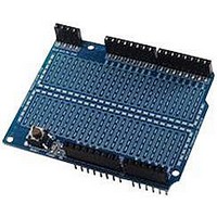
Amicus18 Companion Shield
Manufacturer
AMICUS
Datasheet
1.AMICUS18-COMPANION-SHIELD.pdf
(49 pages)
Specifications of AMICUS18-COMPANION-SHIELD
Silicon Manufacturer
Microchip
Core Architecture
PIC
Core Sub-architecture
PIC18
Features
USB Interface, In Circuit Serial Programming Interface
Kit Contents
Board
Silicon Family Name
PIC
Silicon Core Number
PIC18F25K20
Rohs Compliant
Yes
Lead Free Status / RoHS Status
Lead free / RoHS Compliant
For Use With
PIC18F25K20 Microcontroller


Amicus18 Companion Shield
There are calculations for the values of the resistor and capacitor used, but we won’t go into that here,
RC filter
but a search for
on the internet will produce a huge amount of information. Here’s two of them
that are valid at the time of writing:
http://www.cvs1.uklinux.net/cgi-bin/calculators/time_const.cgi
http://www.sengpielaudio.com/calculator-period.htm
Channel 1 PWM
In this discussion, we’ll be using the compiler’s WriteAnalog macros, which produce either an 8-bit (0
to 255) or 10-bit (0 to 1023) output. It’s important for further RC filter calculations to remember that
the 10-bit PWM macro’s operate at a frequency of 62.5KHz (62,500 Hertz), and the 8-bit PWM macros
operate at a frequency of 125KHz (125,000 Hertz), but only if the Amicus18 board is using it’s default
oscillator speed of 64MHz. If the crystal is replaced with another value type, these frequencies will
section 16
change. See
in the PIC18F25K20 microcontroller’s data sheet for further information concern-
ing the PWM peripherals.
From the paragraph above, we know that if we use the 10-bit PWM macros, we will be operating at a
frequency of 62.5KHz. This relates to a duty cycle of 0.06 milliseconds (ms), or 16 microseconds (us).
If we choose a value of 47 Ohms for our resistor so that we don’t loose too much current, we need a
capacitance value of 340.425nF (0.34uF). There is no common capacitor of that value so we’ll choose a
close value, for example 330nF (0.33uF).
The circuit for a suitable RC low pass filter is shown below:
47Ω
PWM
Voltage Out
Pulses In
R
C
330nF
The Amicus18’s microcontroller has two PWM peripherals; PWM1 from PortC pin RC2, and PWM2 from
PortC pin RC1. Each pin can produce a differing duty cycle (average voltage), but each share the same
frequency.
A demo layout for channel 1 of the PWM is shown below:
43
Crownhill AssociatesLimited 2009 - All Rights Reserved
Version 1.0
06-10-2009
Related parts for AMICUS18-COMPANION-SHIELD
Image
Part Number
Description
Manufacturer
Datasheet
Request
R

Part Number:
Description:
Amicus18 Board
Manufacturer:
AMICUS
Datasheet:

Part Number:
Description:
AMIS30585AGAS-FSK PLC Modem
Manufacturer:
AMI Semiconductor
Datasheet:
Part Number:
Description:
Manufacturer:
AMI Semiconductor
Datasheet:
Part Number:
Description:
Programmable line lock clock generator IC
Manufacturer:
AMI Semiconductor
Datasheet:
Part Number:
Description:
PLL clock generator IC with VCXO
Manufacturer:
AMI Semiconductor
Datasheet:
Part Number:
Description:
Dual-PLL clock generator IC
Manufacturer:
AMI Semiconductor
Datasheet:
Part Number:
Description:
Two-way MP motherboard clock generator IC
Manufacturer:
AMI Semiconductor
Datasheet:
Part Number:
Description:
ADSL DMT Transceiver with ATM Framer and integrated controller
Manufacturer:
AMI Semiconductor
Part Number:
Description:
Integrated ADSL CMOS Analog Front-End Circuit
Manufacturer:
AMI Semiconductor
Datasheet: