EM-LPC1300 EMBEST, EM-LPC1300 Datasheet
EM-LPC1300
Specifications of EM-LPC1300


Related parts for EM-LPC1300


EM-LPC1300 Summary of contents
Page 1
... EM-LPC1300 Development Board User Guide Address:Rm509, Luohu Science&Technology Building, No.85, Taining Road, Luohu District, Shenzhen, 518020, China Telephone: +86-755-25621715 Fax: +86-755-25616057 E-mail: sales.en@embedinfo.com Support: support.en@embedinfo.com Website: http://www.embedinfo.com/en EMBEST CO., LIMITED www.embedinfo.com/en Rev. 1.0 Release: 2010-03-01 1/26 ...
Page 2
... Revision history Rev Date Description 1.0 20100126 Initial version www.embedinfo.com/en 2/26 ...
Page 3
... Use the default factory routine .......................................................................................................................8 2.7 Restore the default factory routine ...............................................................................................................10 2.7.1 Compile the default factory routine.......................................................................................................10 2.7.2 Download the default factory routine....................................................................................................10 CHAPTER 3 EM-LPC1300 DEVELOPMENT BOARD INTRODUCTION ................................................. 11 3.1 Board Interface Overview ............................................................................................................................ 11 3.2 Jumpers Settings........................................................................................................................................... 11 3.3 Hardware Interface Introduction ..................................................................................................................12 3.3.1 JTAG......................................................................................................................................................12 3 ...
Page 4
... I2C Temperature Sensor test ......................................................................................................................18 CHAPTER 5 SOFTWARE DEVELOPMENT AND EXAMPLES..................................................................19 5.1 MDK Introduction........................................................................................................................................19 5.2 Compile routine............................................................................................................................................19 5.2.1 Open a routine.......................................................................................................................................19 5.2.2 Compile the routine ...............................................................................................................................19 5.3 Debug and Download the routine using Emulator .......................................................................................21 5.3.1 Debug and Download the routine using ULINK2 .................................................................................22 www.embedinfo.com/en 4/26 ...
Page 5
... Cortex-M3 project. You can use the Cortex-M3 based EM-LPC1300 Evaluation Board to generate and test application programs for the NXP LPC13xx microcontroller family. With this hands-on process, you can determine the hardware and software requirements for current and future product development ...
Page 6
... Use UART to send and receive data through HyperTerminal. USB Virtual COM port example. USB HID (Human Interface Device) demo. USB HID demo uses functions in rom. USB Memory Storage demo based on USB Mass Storage Class. USB Memory Storage demo uses functions in rom. WatchDog application example. I2C EEPROM Read/write test I2C Temperature sensor test www ...
Page 7
... Manual.pdf Other pdf format files of datasheet 2.3 Version Information The version of the development tools: MDK4.01 2.4 Hardware resource requirements When we test EM-LPC1300, PC recommended the following configuration: 2.0GHz (or higher) of the CPU 512M RAM 2 USB interfaces A serial interface Windows XP operating system KEIL Integrated Development Environment installed 2 ...
Page 8
... It may redisplay the tip information,so you can choose the other ones test the other function. Now we illustrate how to test every function of the board and the corresponding test phenomenon based on the number from zero to five. ***************************************************************** * * Welcome to Embest * * This is EM-LPC1300 test * * arm.embedinfo.com * * 0-LED test 1-BUTTON test * * ...
Page 9
... It displays message “I2C EEPROM test success!” in the terminal. 5 option: I2C Temperature Sensor test. 1) After typing ‘5’,it displays the brief information about this test in the terminal. -- Basic I2C Temperature Sensor Project V1 EM-LPC1300 -- -- I2C Temperature Sensor test -- -I- Temperature Register value:0x1100 -I- Configuration Register value:0x0 -I- Tos Set Point Register value:0x80 www ...
Page 10
... Thyst Set Point Register value:0x1100 I2C Temperature Sensor test success! 2) This project tests temperature sensor on the board using I2C bus, and read internal four registers. They are Temperature Register,Configuration Register,Tos Set Point Register and Thyst Set Point Register. If display message “I2C Temperature Sensor test success!”, then test success. ...
Page 11
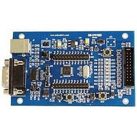
... Chapter 3 EM-LPC1300 Development Board Introduction 3.1 Board Interface Overview LPC1343FBD48 MiniUSB UART J1 Mini USB B Connector J2 GND J3 UART J4 Processor External Round Cable J5 Processor External Round Cable J6 JTAG Interface U1 voltage regulator(1A output current) U2 LPC1343FBD48 Chip D1 Power LED0 D2 LED1 D3 LED2 3.2 Jumpers Settings ID Name ...
Page 12
... A 64kbit EEPROM is connected to the I2C bus in EM-LPC1300 board. 3.3.5 LM75 Temperature Sensor A LM75 Temperature Sensor is connected to the I2C bus in EM-LPC1300 board. 3.3.6 LED EM-LPC1300 provides 8 LEDs D2…9, they respectively connect with PIO2.0…7 IO pins, and they can be used for user output. It also contains a power LED D0. www.embedinfo.com/en 12/26 ...
Page 13
... EM-LPC1300 board. Test cases’ functions, most of those are easy to understand. You can get the details about testing introductions and phenomenon from the readme.txt files in the projects or get them by view the EM-LPC1300 UserManual V1.0.doc documents. ...
Page 14
... Source code location: 03-Software\Examples\04-SSP Test description: The SSP project is a simple program to test SSP LOOPBACK mode on the EM-LPC1300 board. There are three modes in SSP: loopback, master or slave. Here are the combination of all the tests. You need to modify the setting in ssp.h first in order to configure the proper mode for testing ...
Page 15
... USB CDC test Source code location: 03-software\Examples\08-USB_CDC Test description: The Virtual COM port project is a demo program for using the EM-LPC1300 board. It demonstrates an USB Virtual COM port based on a Windows USB host driver (usbser.sys). Test phenomenon: Connnect board with PC COM using USB cable. Build the program and download it inside the evaluation board ...
Page 16
... USB HID ROM test Source code location: 03-software\Examples\10-USB_HID_rom Test description: This project is also a USB HID demo program using the EM-LPC1300 board. The only difference is that pll and pin init function program used are all placed in the BOOT ROM. They are download by ULINK2 or other debugging tools previously and their memory address are determined at the compile time ...
Page 17
... USB Memory Storage Rom test Source code location: 03-software\Examples\12-USB_Mem_rom Test description: The Memory project is a demo program for the Embest EM-LPC1300 Board using the NXP LPC1343 Microcontroller. It demonstrates an USB Memory based on USB Mass Storage Class. The only difference is that pll and pin init function program used are all placed in the BOOT ROM ...
Page 18
... Test phenomenon: Build the program and download it inside the evaluation board. Open PC HyperTerminal and push RESET button. If test success,it may display the four registers’ value in the terminal. Phenomenon is as follows. -- Basic I2C Temperature Sensor Project V1 EM-LPC1300 -- -- I2C Temperature Sensor test -- -I- Temperature Register value:0x1280 -I- Configuration Register value:0x0 ...
Page 19
... Processor. It has a configuration wizard for startup code and integrates flash program module, powerful device simulation, performance analyzer and so on. You can obtain MDK software from the CD released with EM-LPC1300 Evaluation Board in the directory of 04-tools\Realview MDK4.01, or you can download the latest version from Keil website www.keil.com. Double click the installation file setup.exe; finish Keil μVision4 installation under the guidance of the installation wizard ...
Page 20
... D:\Keil\ARM\BIN40\fromelf.exe specify the path of fromelf.exe, it will convert axf file to bin file --bin –o ./obj/Embest_LPC1300.bin ./obj/Embest_LPC1300.axf www.embedinfo.com/en export bin file the directory and file name of the bin file you want to create the directory and file name of the axf file you want to convert ...
Page 21
... MicroLIB" need to be selected. Click Project->Options for Target and select this option in the "Target" tab. 4) Click project->build, or click the shortcut button to build the routine. 5.3 Debug and Download the routine using Emulator The precondition for the next steps is that you have bought or owned a corresponding hardware Emulator. www.embedinfo.com/en 21/26 ...
Page 22
... When ULINK2 connects to the Development Board, if the RUN and COM indicator lights first change to blue and then go out, and the USB indicator light has always been red, this proves that ULINK2 is no problem. In addition, you can use the next way to check ULINK2. Click the Settings button in the Debug TAB, if the red marked part appears, it proves that ULINK2 is no problem ...
Page 23
... Check that whether ULINK2 can detect the development board or not, optional. Click the Settings button in the Debug TAB, if the red marked part appears, it proves that ULINK2 has detected the development board. 4) Set the Flash Programmer, configure the Utilities TAB. Then click Settings button, it appears: www.embedinfo.com/en 23/26 ...
Page 24
... If nothing is in the Programming Algorithm, then you should add the corresponding Flash programming algorithm by clicking the Add button, as follows: After you choose a Flash Programming Algorithm, then Click Add button. 5) Start to Debug the routine by clicking shortcut button the status of the debug as follows: www.embedinfo.com/en or clicking Debug->Start/Stop Debug Session, 24/26 ...
Page 25
... Download the routine using ULINK2 1) Check the Flash Programmer’s setting www.embedinfo.com/en 25/26 ...
Page 26
... Start to Download by click Flash->Download or the shortcut button as follows: www.embedinfo.com/en 26/26 ...