EM-LPC1300 EMBEST, EM-LPC1300 Datasheet - Page 13
EM-LPC1300
Manufacturer Part Number
EM-LPC1300
Description
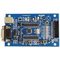
NXP LPC1300 ARM Cortex-M3 Evaluation Board
Manufacturer
EMBEST
Datasheet
1.EM-LPC1300.pdf
(26 pages)
Specifications of EM-LPC1300
Silicon Manufacturer
NXP
Core Architecture
ARM
Core Sub-architecture
Cortex-M3
Features
RS232, USB, JTAG Interface, 12MHz XTAL Frequency
Silicon Core Number
LPC13xx
Silicon Family Name
LPC13xx


Chapter 4 Software Resources Introduction
There are 14 test cases in the CD-ROM provided. The directory is 03-software\examples. You can find 15 folders
in this directory. The Common folder contains common source files and head files. The other 14 items are all test
cases used to test the peripherals or functions of the EM-LPC1300 board.
Test cases’ functions, most of those are easy to understand. You can get the details about testing introductions and
phenomenon from the readme.txt files in the projects or get them by view the EM-LPC1300 UserManual
V1.0.doc documents.
4.1 LED Blinky test
4.2 GPIO test
4.3 PMU test
Source code location: 03-Software\Examples\01-Blinky
Test description: This example describes how to use 16-bits timer to achieve LED1 blinky.
Test phenomenon: Build the program and download it inside the evaluation board.Open PC
HyperTerminal and push RESET button, you will see the phenomenon below.
Then, the LED1 of the board will blinky.
Reference manual: EM-LPC13xx Reference Manual.pdf
Source code location: 03-Software\Examples\02-GPIO
Test description: This example describes how to use GPIO port to achieve input event interrupt. GPIO
ports set as as input event,single edge trigger, active high.
Test phenomenon: Build the program and download it inside the evaluation board. Open PC
HyperTerminal and push RESET button, you will see the phenomenon below.
Reference manual: EM-LPC13xx Reference Manual.pdf
Source code location: 03-Software\Examples\03-PMU
Test description: This example describes how to configure PMU to put some of the peripheral in sleep
mode. It also demonstrates how to setup wakeup source before sleep or deep sleep.
Test phenomenon: Build the program and download it inside the evaluation board. Open PC
HyperTerminal and push RESET button, you will see the phenomenon below.
Press 'BOOT' button on the board may trigger a interrupt. It displays message
" PIOINT0_IRQHandler!" in the terminal.
-- Basic Blinky Project V1.0 --
-- EM-LPC1300 --
-- LED1 blinky test --
-- Basic GPIO Project V1.0 --
-- EM-LPC1300 --
-- GPIO port single edge trigger interrupt test --
-- Basic PMU Project V1.0 --
www.embedinfo.com/en
13/26
Related parts for EM-LPC1300
Image
Part Number
Description
Manufacturer
Datasheet
Request
R

Part Number:
Description:
MIC OMNI .9-10VDC -36DB SENS
Manufacturer:
Knowles Acoustics
Datasheet:
Part Number:
Description:
MIC OMNI .9-10VDC -38.5DB SENS
Manufacturer:
Knowles Acoustics
Datasheet:

Part Number:
Description:
MIC ELECTRET OMNI HIGH SENSITVTY
Manufacturer:
Knowles Acoustics
Datasheet:

Part Number:
Description:
MIC ELECTRET OMNI HISENS W/LEADS
Manufacturer:
Knowles Acoustics
Datasheet:
Part Number:
Description:
Microphone
Manufacturer:
Knowles Acoustics
Datasheet:
Part Number:
Description:
Microphones 3.61 X 3.61 X 2.21MM -68.5 SENS, 12B PORT
Manufacturer:
Knowles Acoustics
Datasheet:
Part Number:
Description:
Microphones 3.61 X 3.61 X 2.21MM -56 SENS, 12B PORT
Manufacturer:
Knowles Acoustics
Datasheet:
Part Number:
Description:
Microphones 3.61 X 3.61 X 2.21MM -56 SENS, 12SL PORT
Manufacturer:
Knowles Acoustics
Datasheet:
Part Number:
Description:
Microphones 3.61 X 3.61 X 2.21MM -58 SENS, 12SL PORT
Manufacturer:
Knowles Acoustics
Datasheet:
Part Number:
Description:
Microphones 3.61 X 3.61 X 2.21MM -52 SENS 12KP PORT
Manufacturer:
Knowles Acoustics
Datasheet:
