EM-LPC1300 EMBEST, EM-LPC1300 Datasheet - Page 8
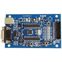
EM-LPC1300
Manufacturer Part Number
EM-LPC1300
Description
NXP LPC1300 ARM Cortex-M3 Evaluation Board
Manufacturer
EMBEST
Datasheet
1.EM-LPC1300.pdf
(26 pages)
Specifications of EM-LPC1300
Silicon Manufacturer
NXP
Core Architecture
ARM
Core Sub-architecture
Cortex-M3
Features
RS232, USB, JTAG Interface, 12MHz XTAL Frequency
Silicon Core Number
LPC13xx
Silicon Family Name
LPC13xx


2.6 Use the default factory routine
Now we illustrate how to test every function of the board and the corresponding test phenomenon based on the
number from zero to five.
1) After typing ‘0’ in the terminal using PC keyboard, the LED1(D2) starts to blinky. Time delay between two
2) Then, the brief information about this function test will be displayed in the terminal.
1) After typing ‘1’,it displays the brief information about this test in the terminal.
2) Pressing ‘BOOT’ button(K1) on the board can triggers one interrupt. Its interrupt service routine displays
flashes is controlled by timer16.
JTAG Debugger Connection: One end connected to JTAG interface on the board, the other end connected to
PC.
Serial Port Receive Settings: In the PC, run HyperTerminal serial communication program, select the serial
port used and set the following parameters (to set status: Baud rate (115200), data bits (8 bits), stop bits (1
bit), parity bit (no ), data flow control (no)).
Set environment according to section 2.5, power on the development board and press ' reset' button.
At this time, the HyperTerminal may display the information about the function of this board,which need to
be tested. See it as below. Every item of board's functions has a number.They are sorted according the
number from digital '0' to '5'. You need to type one number of them so as to test the corresponding function
using PC keyboard after resetting the board.
Note: after testing one function of the bord, you need to reset the board by pressing the 'RESET' button of
the board. It may redisplay the tip information,so you can choose the other ones so as to test the other
function.
0 option: test LED also test the function of Timer16 of the board.
1 option: test the BOOT button onthe board.
*****************************************************************
-- Basic Blinky Project V1.0 --
-- EM-LPC1300 --
-- LED1 blinky test --
-- Basic GPIO Project V1.0 --
-- EM-LPC1300 --
-- GPIO port single edge trigger interrupt test --
-- Please press 'BOOT' button on the board! --
*
*
*
*
*
*
*
*
*
*
*
****************************************************************
Please input number from keyboard
Welcome to Embest
This is EM-LPC1300 test
arm.embedinfo.com
0-LED test
4-I2C EEPROM test
1-BUTTON test
5-I2C Temperature Sensor test
2-UART test
3-USB Memory test
www.embedinfo.com/en
*
*
*
*
*
*
*
*
*
*
*
8/26
Related parts for EM-LPC1300
Image
Part Number
Description
Manufacturer
Datasheet
Request
R

Part Number:
Description:
MIC OMNI .9-10VDC -36DB SENS
Manufacturer:
Knowles Acoustics
Datasheet:
Part Number:
Description:
MIC OMNI .9-10VDC -38.5DB SENS
Manufacturer:
Knowles Acoustics
Datasheet:

Part Number:
Description:
MIC ELECTRET OMNI HIGH SENSITVTY
Manufacturer:
Knowles Acoustics
Datasheet:

Part Number:
Description:
MIC ELECTRET OMNI HISENS W/LEADS
Manufacturer:
Knowles Acoustics
Datasheet:
Part Number:
Description:
Microphone
Manufacturer:
Knowles Acoustics
Datasheet:
Part Number:
Description:
Microphones 3.61 X 3.61 X 2.21MM -68.5 SENS, 12B PORT
Manufacturer:
Knowles Acoustics
Datasheet:
Part Number:
Description:
Microphones 3.61 X 3.61 X 2.21MM -56 SENS, 12B PORT
Manufacturer:
Knowles Acoustics
Datasheet:
Part Number:
Description:
Microphones 3.61 X 3.61 X 2.21MM -56 SENS, 12SL PORT
Manufacturer:
Knowles Acoustics
Datasheet:
Part Number:
Description:
Microphones 3.61 X 3.61 X 2.21MM -58 SENS, 12SL PORT
Manufacturer:
Knowles Acoustics
Datasheet:
Part Number:
Description:
Microphones 3.61 X 3.61 X 2.21MM -52 SENS 12KP PORT
Manufacturer:
Knowles Acoustics
Datasheet:
