FLASH-CAN-64P-350-PMC Fujitsu, FLASH-CAN-64P-350-PMC Datasheet
FLASH-CAN-64P-350-PMC
Specifications of FLASH-CAN-64P-350-PMC


Related parts for FLASH-CAN-64P-350-PMC


FLASH-CAN-64P-350-PMC Summary of contents
Page 1
... Fujitsu Microelectronics Europe User Guide FLASH-CAN-64P-350-PMC F²MC-16LX/FX FAMILY EVALUATION BOARD FMEMCU-UG-960008-10 USER GUIDE ...
Page 2
... Revision History Date 20.06.2007 V1.0, DGo, First Release This document contains 29 pages. UG-960008-10 FLASH-CAN-64P-350-PMC Revision History Issue - 2 - © Fujitsu Microelectronics Europe GmbH ...
Page 3
... Product. Should one of the above stipulations be or become invalid and/or unenforceable, the remaining stipulations shall stay in full effect © Fujitsu Microelectronics Europe GmbH FLASH-CAN-64P-350-PMC Warranty and Disclaimer - 3 - UG-960008-10 ...
Page 4
... LIN”A”, LIN”B” Interface connector (X6, X8) .......................................................... 23 6.5 CAN”A”, CAN”B” Interface connector (X10, X11)................................................... 23 6.6 USER-LEDs & LC-Display (optional) ..................................................................... 23 6.7 VG96 connector (X4)............................................................................................. 24 7 SILK-PLOT OF THE BOARD ........................................................................................ 26 8 RELATED PRODUCTS ................................................................................................. 27 9 INFORMATION IN THE WWW....................................................................................... 28 UG-960008-10 FLASH-CAN-64P-350-PMC Chapter 1 Contents - 4 - © Fujitsu Microelectronics Europe GmbH ...
Page 5
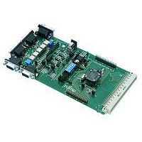
... Overview 2.1 Abstract The FLASH-CAN-64P-350-PMC is a multifunctional evaluation board for the Fujitsu 16-Bit Flash microcontroller MB90350 and MB96350 Series. It can be used stand alone for software development and testing simple target board to work with the emulator system. The board allows the designer immediately to start with the software development before his own final target system is available ...
Page 6
... General Description The FLASH-CAN-64P-350-PMC supports 16-Bit Flash microcontrollers of the MB90350 Series and MB96350 Series. It can be used as a stand alone evaluation board target board for emulator debugger. The evaluation board supports the following package: FPT-64P-M09 / M23 The board is supplied with a socketed 4 MHz crystal as the main oscillation clock. Using the internal PLL of the IC, internal clock rates MHz can be achieved ...
Page 7
... Do not screw the cover too tight (max 0.054 Nm). If you have connectivity problems then please loosen the screws and tighten again the screws equally. Do not clean NQPACK, YQPACK, and YQSOCKET with steam. Cleaning material will contaminate inside of connector. © Fujitsu Microelectronics Europe GmbH FLASH-CAN-64P-350-PMC Chapter 3 Installation - 7 - UG-960008-10 ...
Page 8
... JP48 CAN transceiver A VCC 3V3 / 5V JP49 CAN transceiver B VCC 3V3 / 5V JP52 LIN TLE6259 (2-3) / TLE7259 (1-2) JP53 LIN TLE6259 (2-3) / TLE7259 (1-2) UG-960008-10 FLASH-CAN-64P-350-PMC Chapter 4 Jumpers and Switches Type Jumper 3 pol Jumper 3 pol Jumper 3 pol Jumper 3 pol Jumper 3 pol Jumper 2 pol ...
Page 9
... © Fujitsu Microelectronics Europe GmbH FLASH-CAN-64P-350-PMC Chapter 4 Jumpers and Switches LIN A LIN UG-960008-10 ...
Page 10
... S2/4 S2/5 S2/6 S2/7 (P01) S2/8 (P00) Default: MD0 P00, P01 = default, the Single Chip Run-Mode is selected. Dip-Switch S2 (default setting) UG-960008-10 FLASH-CAN-64P-350-PMC Chapter 4 Jumpers and Switches Setting ON (closed) OFF (open) ON (closed) OFF (open) ON (closed) OFF (open) not connected (OFF) not connected (OFF) ...
Page 11
... JP34 (MCUVcc) OFF (open) Default: JP29 = 1-2, JP34 = closed, By default, the on-board Voltage regulation is used and the microcontroller is powered. © Fujitsu Microelectronics Europe GmbH FLASH-CAN-64P-350-PMC Chapter 4 Jumpers and Switches Description On-board voltage regulation External power-supply from X4 pin 1 Power supply Vcc connected to IC ...
Page 12
... If JP11 and J15 are open, the user has to supply an adequate analogue voltage supply (AVcc and AVss) to the A/D-converter. If JP13 is open, the resistors R11 and R23 define AVRH. By default the resistor network (R11 and R23) is not mounted on the board. UG-960008-10 FLASH-CAN-64P-350-PMC Chapter 4 Jumpers and Switches Description AVcc is connected to Vcc AVcc is disconnected from Vcc ...
Page 13
... JP37 (X1A/P41) 2-3 Default: JP36: 1-4, JP37: 1-2 By default, the 32 kHz subclock-crystal is connected to the microcontroller. © Fujitsu Microelectronics Europe GmbH FLASH-CAN-64P-350-PMC Chapter 4 Jumpers and Switches Pin-out JP36: Description Pin 19 is connected to the 32kHz Subclock (X0A) Pin 19 is used as P40 and is connected to X1-19 and X4-A16 ...
Page 14
... JP8 (UART”B”TxD) OFF (open) ON (closed) JP31 (RTS-CTS) OFF (open) Default: JP6=closed, JP8=closed, JP32 = closed By default, UART3 is used as UART”B”. UG-960008-10 FLASH-CAN-64P-350-PMC Chapter 4 Jumpers and Switches Description 1-2 SOT2 is connected to RS232-transceiver 2-3 SOT2 is connected to LIN-transceiver A 1-2 SIN2 is connected to RS232-transceiver ...
Page 15
... JP9 (LIN enable) JP10 (LIN Master) JP38 (LIN”B”RXD) JP39 (LIN”B”TXD) Default: JP9=open, JP10=open, JP38=open, JP39=open By default, UART8 is not used as LIN-interface. © Fujitsu Microelectronics Europe GmbH FLASH-CAN-64P-350-PMC Chapter 4 Jumpers and Switches Description open LIN-transceiver is disabled closed LIN-transceiver is enabled ...
Page 16
... JP28 (RX2) 2-3 Default: JP27=1-2, JP28=1-2 By default, LED D3 and D4 are connected to Port P32 and P33 of the microcontroller. UG-960008-10 FLASH-CAN-64P-350-PMC Chapter 4 Jumpers and Switches Description TX1 is disconnected from CAN-Transceiver (U7, X10) TX1 is connected to CAN-Transceiver (U7, X10) RX1 is disconnected from CAN-Transceiver (U7, X10) RX1 is connected to CAN-Transceiver (U7, X10) ...
Page 17
... If JP35 (Polarity) is set, than JP4 and JP5 have to be set, too. If the reset LED is steadily on, check the power supply input voltage and the settings for the reset-generation by UART. © Fujitsu Microelectronics Europe GmbH FLASH-CAN-64P-350-PMC Chapter 4 Jumpers and Switches Setting Description 1-2 DTR of UART” ...
Page 18
... JP23 (IN1) Open Default: JP7, JP12, JP14, JP16, JP20, JP23 =closed By default, INT10, INT11, TIN1, IN0, IN1 are connected to the Push buttons. UG-960008-10 FLASH-CAN-64P-350-PMC Chapter 4 Jumpers and Switches Description Reset is triggered immediately Reset is triggered delayed no connection INT10 is connected to Push-button “INT10” ...
Page 19
... Series Flash Mode Async. 4MHz 5. Power on the board 6. Check that the Reset LED is off. Otherwise change the DTR polarity (JP35) and check the power supply voltage. © Fujitsu Microelectronics Europe GmbH FLASH-CAN-64P-350-PMC Chapter 5 Programming the internal Flash MD0 MD1 MD2 ...
Page 20
... After programming the Flash-ROM, switch off the power supply and set back the mode according to the usage of the application, e.g.: Single-Chip Run Mode 9. Power on the board. The user application is started directly. Flash Mode MB90F350 Flash Mode MB96F350 Run Mode: UG-960008-10 FLASH-CAN-64P-350-PMC Chapter 5 Programming the internal Flash Set Device Type MB96F356 FlashCan64P350.mhx MD0 MD1 MD2 ...
Page 21
... In case that another Programming-Tool is used and the Mode-settings have to be done manually then use the following configuration of DIP-switch S2 in order to select the synchronous-serial Flash-programming mode: synchronous Boot-Mode © Fujitsu Microelectronics Europe GmbH FLASH-CAN-64P-350-PMC Chapter 5 Programming the internal Flash P00 1 MD0 3 RST 5 SOT3 7 ...
Page 22
... UART”A” and UART”B”. TXD is the transmit output, RXD is the receive input. The DTR or RTS signal can be used to generate a reset. Please use 1:1 cable for PC-connection. UG-960008-10 FLASH-CAN-64P-350-PMC Chapter 6 Connectors Shield is connected to ground (GND) Centre is connected to positive voltage (+) MCU Pins 1 – ...
Page 23
... Instead of the user-LEDs one alphanumeric LC-Display (optional) can be connected. The following control-signals are reserved LCD LED MCU Port P37 P36 P35 P34 © Fujitsu Microelectronics Europe GmbH FLASH-CAN-64P-350-PMC Chapter 6 Connectors Connectors X6, X8: Connector X10, X11 P33 P32 - 23 - BUS +Ubat 5 9 GND GND CANL 5 ...
Page 24
... P54/AN12/TOT3 14 P55/AN13 15 P56/AN14 16 P42/IN6/RX1/INT9R 17 P43/IN7/TX1 18 Vss 19 P40/X0A 20 P41/X1A 21 MD2 22 MD1 23 MD0 24 P00/AD00/INT8 25 P01/AD01/INT9 26 P02/AD02/INT10 27 P03/AD03/INT11 28 P04/AD04/INT12 29 P05/AD05/INT13 30 P06/AD06/INT14 31 P07/AD07/INT15 32 P10/AD08/TIN1 UG-960008-10 FLASH-CAN-64P-350-PMC Chapter 6 Connectors VG (X4) MB90350 - B13 35 C13 36 A14 37 B14 38 C14 39 A15 40 A10 41 B10 42 C10 43 A11 44 B11 45 C11 46 A12 ABC3 50 (A16) ...
Page 25
... Vss 19 P40/X0A 20 P41/X1A 21 MD2 22 MD1 23 MD0 24 P00/AD00/INT8/SCK7R 25 P01/AD01/INT9/SOT7R 26 P02/AD02/INT10/SIN7R 27 P03/AD03/INT11/SCK8R 28 P04/AD04/INT12/SOT8R 29 P05/AD05/INT13/SIN8R 30 P06/AD06/INT14/PPG10R 31 P07/AD07/INT15/PPG11R 32 P10/AD08/CKOT1/TIN1 © Fujitsu Microelectronics Europe GmbH FLASH-CAN-64P-350-PMC Chapter 6 Connectors VG (X4) MB90 - 33 P11/AD09/CKOTX1/TOT1 - 34 P12/AD10/INT11/SIN3 B13 35 P13/AD11/SOT3 C13 36 P14/AD12/SCK3 A14 37 P15/AD13/SIN2R/INT7R B14 38 P16/AD14/SOT2R C14 39 P17/AD15/SCK2R A15 40 P20/A16/PPG12/CKOT1R A10 41 P21/A17/PPG13 ...
Page 26
... Silk-Plot of the Board Pin 1 Pin 2 X1 Pin 32 Pin 31 X12 Power- Jack CAN”B” X11 INT10 CAN”A” X10 UG-960008-10 FLASH-CAN-64P-350-PMC Chapter 7 Silk-Plot of the Board X4 VG96-male MCU 90F352 4MHz MAX232 optional: LCD MAX232 User-LEDs (P30-P37) TIN1 IN0 IN1 Reset INT11 LIN” ...
Page 27
... Related Products < FLASH-CAN-64P-350-PMC < FLASH-CAN-64P-350-PMC1 Evaluation board for MB90350 and MB96350 Series with < NQPack64sb < HQPack64sb140 16LX Series (MB90350) < MB2147-01 < MB2147-20 < MB2147-540 < MB90V340xxx < MB90V340A-101 < MB90V340A-102 < MB90F352(C) < MB90F352(C)S 16FX Series (MB96350) < MB2198-01 < MB2198-500 < MB2198-504 < MB96V300 < MB96F356RWAPMC < MB96F356RSAPMC © Fujitsu Microelectronics Europe GmbH FLASH-CAN-64P-350-PMC Chapter 8 Related Products ...
Page 28
... Linear Products: Power Management, A/D and D/A Converters http://www.fujitsu.com/emea/services/microelectronics/linears/ Media Products: SAW filters, acoustic resonators and VCOs http://www.fujitsu.com/emea/services/microelectronics/saw/ For more information about FUJITSU MICROELECTRONICS http://www.fujitsu.com/emea/services/microelectronics/ UG-960008-10 FLASH-CAN-64P-350-PMC Chapter 9 Information in the WWW - 28 - © Fujitsu Microelectronics Europe GmbH ...
Page 29
... According to the European WEEE-Directive and its implementation into national laws we take this device back. For disposal please send the device to the following address: Fujitsu Microelectronics Europe GmbH Warehouse/Disposal Monzastraße 4a 63225 Langen © Fujitsu Microelectronics Europe GmbH FLASH-CAN-64P-350-PMC Chapter 9 Information in the WWW Recycling - 29 - UG-960008-10 ...