FLASH-CAN-64P-350-PMC Fujitsu, FLASH-CAN-64P-350-PMC Datasheet - Page 22
FLASH-CAN-64P-350-PMC
Manufacturer Part Number
FLASH-CAN-64P-350-PMC
Description
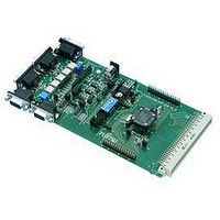
Fujitsu 16-Bit Multifunctional Board
Manufacturer
Fujitsu
Datasheet
1.FLASH-CAN-64P-350-PMC.pdf
(29 pages)
Specifications of FLASH-CAN-64P-350-PMC
Silicon Manufacturer
Fujitsu
Features
In-Circuit Serial Flash Programming, High-Speed CAN Transceiver, UART Interfaces
Silicon Family Name
MB90350, MB96350
Silicon Core Number
MB90F35x, MB96F35x
Rohs Compliant
No
Lead Free Status / RoHS Status
Contains lead / RoHS non-compliant


6 Connectors
6.1 Power connector (X12)
The following figure shows the power connection jack X12. This connector is used to
connect an external unregulated DC power supply voltage (9 V - 12 V DC) to the evaluation
board.
Connector X12:
It is recommended to use 9 V to keep the power dissipation to a minimum. Otherwise, an
additional heat sink for the linear voltage regulator might be necessary.
6.2 Edge connector (X1, X2)
All pins of the microcontroller are directly connected to X1 and X2 as follows:
The odd pin numbers are located on the one side and the even pin numbers are located on
the other side of the connector.
On the PCB, the corresponding pin numbers of the IC are written next to the connector pins.
6.3 UART”A”, UART”B” connector (X3, X5)
Two 9-pin D-Sub female connectors are used
for the serial interface UART”A” and UART”B”.
TXD is the transmit output, RXD is the receive input.
The DTR or RTS signal can be used to generate a reset.
Please use 1:1 cable for PC-connection.
UG-960008-10
X2 (33 – 64)
Connector
X1 (1 – 32)
FLASH-CAN-64P-350-PMC
Centre is connected to positive voltage (+)
Chapter 6 Connectors
Shield is connected to ground (GND)
MCU Pins
Connectors X3, X5:
33 – 64
1 – 32
- 22 -
© Fujitsu Microelectronics Europe GmbH
5
9
GND DTR RxD TxD
CTS RTS DSR
1
6
Related parts for FLASH-CAN-64P-350-PMC
Image
Part Number
Description
Manufacturer
Datasheet
Request
R

Part Number:
Description:
IC MCU FLASH 8KX16 CAN 28DIP
Manufacturer:
Microchip Technology
Datasheet:

Part Number:
Description:
IC MCU FLASH 16KX16 CAN 28SOIC
Manufacturer:
Microchip Technology
Datasheet:

Part Number:
Description:
IC MCU FLASH 16KX16 CAN 40DIP
Manufacturer:
Microchip Technology
Datasheet:

Part Number:
Description:
IC MCU CAN FLSH 16K 40MHZ 44TQFP
Manufacturer:
Microchip Technology
Datasheet:
Part Number:
Description:
IC PIC MCU FLASH 64K 28SOIC
Manufacturer:
Microchip Technology
Datasheet:

Part Number:
Description:
IC PIC MCU FLASH 64K 28-QFN
Manufacturer:
Microchip Technology
Datasheet:

Part Number:
Description:
IC PIC MCU FLASH 32KX16 64TQFP
Manufacturer:
Microchip Technology
Datasheet:

Part Number:
Description:
IC PIC MCU FLASH 64K 44-QFN
Manufacturer:
Microchip Technology
Datasheet:
Part Number:
Description:
IC PIC MCU FLASH 64KX16 64TQFP
Manufacturer:
Microchip Technology
Datasheet:
Part Number:
Description:
IC PIC MCU FLASH 128K 44TQFP
Manufacturer:
Microchip Technology
Datasheet:
Part Number:
Description:
IC PIC MCU FLASH 24KX16 64TQFP
Manufacturer:
Microchip Technology
Datasheet:
Part Number:
Description:
IC PIC MCU FLASH 32KX16 64TQFP
Manufacturer:
Microchip Technology
Datasheet:

Part Number:
Description:
IC PIC MCU FLASH 32KX16 80TQFP
Manufacturer:
Microchip Technology
Datasheet:

Part Number:
Description:
IC ARM7 MCU FLASH 64K 100LQFP
Manufacturer:
NXP Semiconductors
Datasheet:
Part Number:
Description:
IC ARM7 MCU FLASH 128K 100LQFP
Manufacturer:
NXP Semiconductors
Datasheet: