SK-96320-80PMC Fujitsu, SK-96320-80PMC Datasheet - Page 20
SK-96320-80PMC
Manufacturer Part Number
SK-96320-80PMC
Description
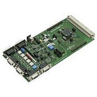
F2MC-16FX Family Evaluation Board
Manufacturer
Fujitsu
Datasheet
1.SK-96320-80PMC.pdf
(34 pages)
Specifications of SK-96320-80PMC
Silicon Manufacturer
Fujitsu
Features
In-Circuit Serial Flash Programming, Onboard Voltage Supervisor
Silicon Family Name
MB96F32x
Silicon Core Number
MB96320
Peak Reflow Compatible (260 C)
No
Lead Free Status / RoHS Status
Contains lead / RoHS non-compliant


3.13 Reset-Generation (JP: 3, 4, 5, 7, 24, 35)
In addition to the internal Power-On reset, the microcontroller can be reset by an external
reset circuit (Voltage Monitor) and also by a RS232 interface.
JP3, JP5 As well the DTR-line as the RTS-Line of UART”A” or UART”B” can be used
JP4
JP7
JP24
JP35
Default: JP24 is closed; JP3, JP4, JP5 and JP35 are open
By default, the external reset is enabled and set to immediate reset, the reset by UART is
disabled.
Note:
While a reset signal is asserted the red Reset-LED D14 is lit.
During normal operation, this LED should be off!
If JP35 (Polarity) is set, JP4 and either JP3 or JP5 have to be set, too.
If the reset LED is steadily on, check the power supply input voltage and the settings for the
reset-generation by UART.
FMEMCU-UG-960010-12
(Reset imm./delayed)
JP3 (DTR / RTS “A”)
JP5 (DTR / RTS “B”)
JP4 (UART”A”/”B”)
JP24 (Main Reset)
JP35 (Polarity)
Jumper
reset is generated to avoid accidental resets.
to generate a system reset.
This jumper selects whether the DTR/RTS line from UART”A” or UART”B”
will generate a system reset.
This solder jumper selects between normal (immediate) reset and delayed reset.
In delayed reset mode, the reset button has to be held down for 2 sec before a
Open this jumper if no external Reset shall be generated.
In this case only the internal reset is active (e.g.: power-on)
The signal on the DTR/RTS line can be negated with this jumper.
Remove the jumper in order to disable the RS232 reset circuit.
JP7
Setting
Closed
Open
1-2
2-3
1-2
2-3
1-2
2-3
1-2
2-3
1-2
2-3
Chapter 3 Jumpers and Switches
SK-96320-80PMC User Guide
Description
DTR of UART”A” is selected
RTS of UART”A” is selected
UART”A” is used to generate Reset
UART”B” is used to generate Reset
DTR of UART”B” is selected
RTS of UART”B” is selected
Reset is applied immediately when SW6 is pressed
Reset is applied when SW6 is pressed >2sec
External Reset generation is active
No external Reset generation
No negation for the DTR/RTS signal
DTR/RTS signal is negated
- 20 -
© Fujitsu Microelectronics Europe GmbH
Related parts for SK-96320-80PMC
Image
Part Number
Description
Manufacturer
Datasheet
Request
R

Part Number:
Description:
Fujitsu Media Devices Limited [NMOS 1- CHANNEL, 13-BIT AND 3-CHANNEL, 6-BIT D/A CONVERTER]
Manufacturer:
Fujitsu
Datasheet:
Part Number:
Description:
Fujitsu Media Devices Limited [32-bit RISC Microcontroller]
Manufacturer:
Fujitsu
Datasheet:
Part Number:
Description:
Fujitsu Media Devices Limited [MOS 262,144 BIT DYNAMIC RANDOM ACCESS MEMORY]
Manufacturer:
Fujitsu
Datasheet:
Part Number:
Description:
Fujitsu Media Devices Limited [PROGRAMMABLE TIMER]
Manufacturer:
Fujitsu
Datasheet:
Part Number:
Description:
Fujitsu Media Devices Limited [MOS Universal Asynchronous receiver/transmitter(UART)]
Manufacturer:
Fujitsu
Datasheet:
Part Number:
Description:
Fujitsu Media Devices Limited [16M (2M X 8/1M X 16) BIT]
Manufacturer:
Fujitsu
Datasheet:
Part Number:
Description:
KIT, STARTER, MB95200/210/220
Manufacturer:
Fujitsu
Datasheet:
Part Number:
Description:
SWITCHING REGULATOR CONTROLLER
Manufacturer:
Fujitsu
Datasheet:
Part Number:
Description:
QUAD OPERATIONAL AMPLIFIER
Manufacturer:
Fujitsu
Datasheet:
Part Number:
Description:
Switching Regulator Controller (Switchable between push-pull and single-end functions)
Manufacturer:
Fujitsu
Datasheet:
Part Number:
Description:
HIGH-SPEED CMOS SINGLE CHIP 4-BIT MICROCOMPUTER MB88505HHIGH-SPEED CMOS SINGLE CHIP 4-BIT MICROCOMPUTER
Manufacturer:
Fujitsu
Datasheet:
Part Number:
Description:
MOS 1024 BIT NON VOLATILE RANDOM ACCESS MEMORY
Manufacturer:
Fujitsu
Datasheet:
Part Number:
Description:
Schottky TTL 2048-Bit Bipolar Programmable Read-Only Memory
Manufacturer:
Fujitsu
Datasheet:
Part Number:
Description:
QUAD COMPARATOR
Manufacturer:
Fujitsu
Datasheet: