HI28B2039 FerriShield, HI28B2039 Datasheet - Page 13
HI28B2039
Manufacturer Part Number
HI28B2039
Description
FERRITE BEAD
Manufacturer
FerriShield
Datasheet
1.HI28B2039.pdf
(40 pages)
Specifications of HI28B2039
Impedance
410ohm
Width (latch Included)
45.7mm
Internal Diameter
11mm
Frequency
100MHz
Size
43.2 Mm X 50.8 Mm X 45.7 Mm
Lead Free Status / RoHS Status
Lead free / RoHS Compliant


For attenuation properties by frequency, see page 32
28 material
.275 (6,94)
high impedance sleeve snap
high impedance sleeve snap
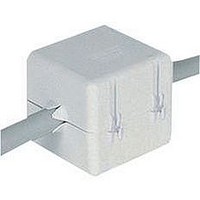
USB cable sleeve snap
For use with USB I/O USB 2.0 Electrical Test Specification, sections 7.0 and 8.0
PART No.
PART No.
PART No.
HI28B2039
HF28B2039
HW28B2039
HA28B2039
HI28B2038
HF28B2038
HW28B2038
HA28B2038
USB28B2034
USB28B2034K
WITH OPTIONAL MOUNTING BASES.
High impedance ferrite assembly for large scale applications containing
high data rates and microprocessor harmonics/spurious signals well
beyond the operating frequency. Excellent for telecommunications
switching applications, local area networks (LANs) and distribution
system integration. The basic version simply clamps into position around
cables and wiring. May also be mounted with a flat-head screw through
the .120” (3,0mm) diameter hole in the bottom by temporarily removing
lower ferrite half.
Other mounting options include a foam adhesive base, a button mount
base sized for a .150” (3.8 mm) diameter hole, and a hardware mounting
plate for screw or rivet attachment. The adhesive mount base and button
mount base options are preassembled. The hardware mounting base
may be press-fitted into the receptacle on the bottom of the case during
installation in one of four positions at 90° increments for alternative
assembly configurations.
WITH VARIABLE DIAMETER END PORTS AND
OPTIONAL MOUNTING BASES.
High impedance ferrite assembly with exactly the same characteristics
as the high impedance sleeve snaps above, except that the entry/
exit end ports are surrounded with flexible spring flutes to grip a range
of cable diameters from .250” to .435” (6,4 to 11,0mm). Excellent for
telecommunications switching applications, local area networks (LANs)
and distribution system integration. The basic version simply clamps
into position around cables and wiring. May also be mounted with a flat-
head screw through the .120” (3,0mm) diameter hole in the bottom by
temporarily removing lower ferrite half.
Other mounting options include a foam adhesive base, a button mount
base sized for a .150” (3.8mm) diameter hole, and a hardware mounting
plate for screw or rivet attachment. The adhesive mount base and button
mount base options are preassembled. The hardware mounting base
may be press-fitted into the receptacle on the bottom of the case during
installation in one of four positions at 90° increments for alternative
assembly configurations.
WITH VARIABLE DIAMETER END PORTS.
range of common USB I/O cable diameters; variable diameter end ports
allow for different types of cable insulation covers measuring .125” to
.179” (3,0 - 4,5mm).
Simple snap-on installation. Available with optional adhesive pad on
bottom, and in standard gray (PMS #413) and black colors.
OPTIONAL BUTTON MOUNT BASE
.275 (6,94)
.275 (6,94)
.275 (6,94)
(4,26)
. 1 68
OPTIONAL BUTTON MOUNT BASE
OPTIONAL BUTTON MOUNT BASE
(Preassembled)
OPTIONAL BUTTON MOUNT BASE
.070 (1,78)
Description
Basic
Button Mount
Hardware Mount
Adhesive Mount
(4,26)
(4,26)
Description
. 1 68
Basic
Button Mount
Hardware Mount
Adhesive Mount
. 1 68
(Preassembled)
(Preassembled)
(4,26)
. 1 68
USB28B2034A
USB28B2034KA
.070 (1,78)
.070 (1,78)
(Preassembled)
w/Adhesive
.070 (1,78)
wideband ferrites- up to 1GHz applications
.150 (3,81)
.150 (3,81)
.150 (3,81)
.150 (3,81)
1.700
1.700
1.700
1.700
1.700
1.700
1.700
1.700
.585
.585
A
A
A
.060 (1,52)
.060 (1,52)
43,2
43,2
43,2
43,2
14,9
14,9
13
43,2
43,2
43,2
43,2
.375 (9,52)
.375 (9,52)
.060 (1,52)
.060 (1,52)
OPTIONAL HARDWARE MOUNT BASE
OPTIONAL HARDWARE MOUNT BASE
(To be assembled during installation)
1.250
1.250
(To be assembled during installation)
2.000
2.000
2.000
2.000
1.780
1.780
1.780
1.780
.375 (9,52)
.375 (9,52)
B (ref.)
OPTIONAL HARDWARE MOUNT BASE
OPTIONAL HARDWARE MOUNT BASE
(To be assembled during installation)
(To be assembled during installation)
Specifically sized to fit the
B
B
31,8
31,8
50,8
50,8
50,8
50,8
45,2
45,2
45,2
45,2
1.25 (31,8)
1.25 (31,8)
.585
.585
1.800
1.800
1.800
1.800
1.25 (31,8)
1.25 (31,8)
1.800
1.800
1.800
1.800
C
14,9
14,9
C
C
45,7
45,7
45,7
45,7
45,7
45,7
45,7
45,7
.250
.250
. 1 25 (3,18)
.125 (3,18)
D
. 1 25 (3,18)
. 1 25 (3,18)
6,4
6,4
.500
.500
.500
.500
.428
.428
.428
.428
D
D
.120
.120
OPTIONAL ADHESIVE MOUNT BASE
12,7
12,7
12,7
12,7
10,9
10,9
10,9
10,9
E
3,0
3,0
.030" (0,76)
OPTIONAL ADHESIVE MOUNT BASE
1.70 (43,2)
.140
.140
.140
.140
(Preassembled)
.468
.468
.468
.468
OPTIONAL ADHESIVE MOUNT BASE
OPTIONAL ADHESIVE MOUNT BASE
.680
.680
E
B
E
B
F
B
B
17,3
17,3
11,9
11,9
11,9
11,9
3,55
3,55
3,55
3,55
1.70 (43,2)
Optional Adhesive Pad
Patent Nos. 5,003,278 and 5,764,125
(Preassembled)
1.70 (43,2)
1.70 (43,2)
(Preassembled)
(Preassembled)
.032 (0,81)
Mounting receptacle
for button and hardware
mount bases.
Mounting receptacle
for button and hardware
mount bases.
COLOR IMPEDANCE IN OHMS
black
gray
Mounting receptacle
for button and hardware
mount bases.
Mounting receptacle
for button and hardware
mount bases.
A
B
A
A
A
IMPEDANCE IN OHMS
IMPEDANCE IN OHMS
.030 (0,76)
.030 (0,76)
.030 (0,76)
Patent No. 5,003,278
A E
410 @ 100MHz
410 @ 100MHz
410 @ 100MHz
410 @ 100MHz
410 @ 100MHz
410 @ 100MHz
410 @ 100MHz
410 @ 100MHz
220 @ 100MHz
220 @ 100MHz
E
E
E
E
C
C
C
C
C
F
D
D
D
D
D
Related parts for HI28B2039
Image
Part Number
Description
Manufacturer
Datasheet
Request
R

Part Number:
Description:
EMI Connector Gaskets D Shape RFI Shielding Gasket
Manufacturer:
FerriShield
Datasheet:
Part Number:
Description:
EMI Connector Gaskets Shielding Contacts .138 Square
Manufacturer:
FerriShield
Datasheet:
Part Number:
Description:
EMI Connector Gaskets Micro D Shape RFI Shielding Gasket
Manufacturer:
FerriShield
Datasheet:
Part Number:
Description:
EMI Connector Gaskets Rectangular RFI Shielding Gasket
Manufacturer:
FerriShield
Datasheet:
Part Number:
Description:
EMI Connector Gaskets D Shape RFI Shielding Gasket
Manufacturer:
FerriShield
Datasheet:

Part Number:
Description:
EMI Connector Gaskets 25 Pin D-Sub Shield
Manufacturer:
FerriShield
Datasheet:
Part Number:
Description:
EMI Connector Gaskets 37 Pin D-Sub Shield
Manufacturer:
FerriShield
Datasheet:
Part Number:
Description:
EMI Connector Gaskets Rectangular RFI Gasket 24
Manufacturer:
FerriShield
Datasheet:
Part Number:
Description:
EMI Connector Gaskets 9 Pin D-Sub Shield
Manufacturer:
FerriShield
Datasheet:

Part Number:
Description:
EMI Connector Gaskets Rectangular RFI Shielding Gasket
Manufacturer:
FerriShield
Datasheet:
Part Number:
Description:
EMI Connector Gaskets 50 Pin D-Sub Shield
Manufacturer:
FerriShield
Datasheet:
Part Number:
Description:
EMI Connector Gaskets D Shape RFI Shielding Gasket
Manufacturer:
FerriShield
Datasheet:
Part Number:
Description:
EMI Connector Gaskets 15 Pin D-Sub Shield
Manufacturer:
FerriShield
Datasheet:
Part Number:
Description:
EMI Gaskets & Grounding Pads Polyester with Cu-Ni 500KHz-1GHz
Manufacturer:
FerriShield
Datasheet:

Part Number:
Description:
EMI Gaskets & Grounding Pads Hot Melt Adhesive 100MHz-1GHZ
Manufacturer:
FerriShield
Datasheet: