HI28B2039 FerriShield, HI28B2039 Datasheet - Page 6
HI28B2039
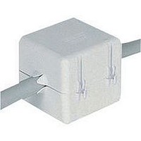
Manufacturer Part Number
HI28B2039
Description
FERRITE BEAD
Manufacturer
FerriShield
Datasheet
1.HI28B2039.pdf
(40 pages)
Specifications of HI28B2039
Impedance
410ohm
Width (latch Included)
45.7mm
Internal Diameter
11mm
Frequency
100MHz
Size
43.2 Mm X 50.8 Mm X 45.7 Mm
Lead Free Status / RoHS Status
Lead free / RoHS Compliant


Product Profile
the simplest, most convenient and most cost-effective solution
for radio frequency interference problems in cables and
connectors. Further, they accomplish both RF attenuation
and suppression of unwanted high frequency oscillations
with no loss in dc or low frequency signal strength.
of ferrous oxide and one or more other powdered metals -
most often manganese, zinc, cobalt or nickel. An extensive
selection of shapes and sizes is already available, and custom
geometries may be manufactured for special situations.
levels possible. Each discrete ferrite formulation results in
a stoichiometric ratio which is its performance characteristic
signature regarding electrical, magnetic and mechanical
relationships. The most common expression of ferrites’
performance capabilities is in terms of their permeability
(µ). This property expresses the ratio of the magnitude of
magnetic induction to magnetizing force. The materials are
normally categorized according to initial permeability (µ i ).
which together serve the common spectrum of today’s
RFI needs.
#28 formulation is recommended, especially when higher
frequency harmonics are a consideration. For frequencies
typified by microprocessor speeds in excess of 100MHz
and harmonics peak interference at nominally 700MHz, #25
formulation is designed to cover this range with even some
effect beyond that. For frequencies from 1 MHz to 30 MHz,
#33 material offers a concentration of impedance in that
range with a decreasing effect above 30 MHz. For microwave
frequencies relating to Bluetooth™ 2.45GHz operations, the
#20 material is available. See figure 1 above.
Ferrite shielding materials are widely accepted as providing
The basic composition of ferrite materials is a combination
There are infinite varieties of formulas and performance
FerriShield has developed four principal formulations
1000
100
fig. 1 Typical attenuation profiles
10
1
1M
For frequencies from 10 MHz to 1 GHz,
TYPICAL PERFORMANCE
FREQUENCY (Hz)
10M
C
B
100M
A
1G
20 Permeability ( i )
#20 Ferrite (Microwave
formula)
125 Permeability ( i )
#25 Ferrite (Specific,
high-frequency formula)
850 Permeability ( i )
#28 Ferrite (Popular,
universal formula)
2700 Permeability ( i )
#33 Ferrite (Specific,
low-frequency formula)
6
Electromagnetic Characteristics
a powerful insertion loss device
makes ferrites effective in RFI/EMI suppression is their
variable sensitivity to frequency. With a ferrite installed as a
suppressor, lower frequencies will pass with no significant
loss. But above the frequency where (tan d / µ ) climbs sharply
(see figure 1), the signal couples with the ferrite to create
an impedance which is quite high compared with the rest
of the circuit. The offending RFI is thus immediately and
consistently blocked out by way of impedance damping
of the unwanted high frequency signals. It is this greater
resistive impedance which allows the basically passive,
apparently simple material to suppress multiple signals in a
variety of application situations.
fig. 2
Impedance comparison
vs. cubic volume.
fig. 3
Two turn loop through
ferrite increases
effective magnetic
path. Impedance
increases by the square
of the number of turns
(N 2 ).
fig. 4
Increased impedance;
multiple turns (N 2 )
vs. one turn through
ferrite; i.e., 2 turns
(2 2 ) = 4 times
impedance
Stated most simply, the operative characteristic which
Related parts for HI28B2039
Image
Part Number
Description
Manufacturer
Datasheet
Request
R

Part Number:
Description:
EMI Connector Gaskets D Shape RFI Shielding Gasket
Manufacturer:
FerriShield
Datasheet:
Part Number:
Description:
EMI Connector Gaskets Shielding Contacts .138 Square
Manufacturer:
FerriShield
Datasheet:
Part Number:
Description:
EMI Connector Gaskets Micro D Shape RFI Shielding Gasket
Manufacturer:
FerriShield
Datasheet:
Part Number:
Description:
EMI Connector Gaskets Rectangular RFI Shielding Gasket
Manufacturer:
FerriShield
Datasheet:
Part Number:
Description:
EMI Connector Gaskets D Shape RFI Shielding Gasket
Manufacturer:
FerriShield
Datasheet:

Part Number:
Description:
EMI Connector Gaskets 25 Pin D-Sub Shield
Manufacturer:
FerriShield
Datasheet:
Part Number:
Description:
EMI Connector Gaskets 37 Pin D-Sub Shield
Manufacturer:
FerriShield
Datasheet:
Part Number:
Description:
EMI Connector Gaskets Rectangular RFI Gasket 24
Manufacturer:
FerriShield
Datasheet:
Part Number:
Description:
EMI Connector Gaskets 9 Pin D-Sub Shield
Manufacturer:
FerriShield
Datasheet:

Part Number:
Description:
EMI Connector Gaskets Rectangular RFI Shielding Gasket
Manufacturer:
FerriShield
Datasheet:
Part Number:
Description:
EMI Connector Gaskets 50 Pin D-Sub Shield
Manufacturer:
FerriShield
Datasheet:
Part Number:
Description:
EMI Connector Gaskets D Shape RFI Shielding Gasket
Manufacturer:
FerriShield
Datasheet:
Part Number:
Description:
EMI Connector Gaskets 15 Pin D-Sub Shield
Manufacturer:
FerriShield
Datasheet:
Part Number:
Description:
EMI Gaskets & Grounding Pads Polyester with Cu-Ni 500KHz-1GHz
Manufacturer:
FerriShield
Datasheet:

Part Number:
Description:
EMI Gaskets & Grounding Pads Hot Melt Adhesive 100MHz-1GHZ
Manufacturer:
FerriShield
Datasheet: